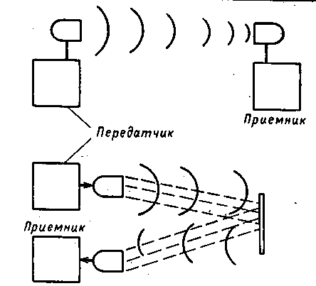
The use of ultrasound is another direction in the development of "Proximity Detectors". In Fig.1 shows such a device. In the upper part of the figure shows a possible configuration where the transmitter and the ultrasound receiver located opposite each other. While nothing prevents ultrasound to fully reach the receiver, the scheme is pending. But, this can prevent the infringer, located between the emitter and the receiver.

Options ultrasonic burglar alarm
Such a device can provide a very high level of reliability. After all, any reduction in the level of the signal from the transmitter or Paget termination of his work in General will be considered by the receiver circuits as a danger. The above examples may occur just at the output of the transducer.
In the lower part of the figure shows another arrangement of receiver and transmitter. In this case, the ultrasound is reflected from the left to the distance of the solid object and arrives at the receiver. The signal emitted by the transmitter must be powerful enough. Naturally, any object that stood in the way of sound, will cause an alarm.
Another way is possible. In this case, the sound reaches the receiver, only reflected from the robber near the transmitter and receiver.
All described methods are good, so choose one which is best suited to your circumstances. Ultrasonic watchman with separate receiver and transmitter
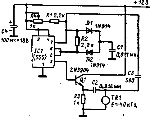
In Fig.1 is a schematic diagram of the ultrasonic transmitter.
It is founded on a 555 type timer and operating frequency determine the values of R1 and R4 and capacitor C1.

Diagram of the ultrasonic transmitter.
The ultrasonic transducer TR1 provides the greatest return on its own resonance frequency, and hence needs to eat it is with this frequency. If during operation of the device, the oscillator frequency of the transmitter will "float" it in some point will reduce the level of the signal emitted by the transmitter, i.e., will cause a false alarm. To increase the stability of the oscillator frequency through a capacitor C3 created feedback. The radiator is like a resonant circuit, the signal which is maximum at the resonance frequency. Thus, the induced positive feedback keeps the generator at the natural frequency of the radiator and narrows the range of adjustment of its resistor R4. To improve frequency stability must feed the circuit from a stabilized power supply. But I must say that the unstable power supply voltage to 1 V cause no care frequency or decrease the output level.
The transmitter is collected on a Board of insulating material and placed in a metal or plastic case. During installation, observe the neatness, and the overall scheme is not critical to the disposition of parts, and design of pick up at their discretion. Because of parts in the transmitter a bit, it would be nice and cost, and an emitter positioned within the housing. Besides long connecting wires to the emitter, adversely affect the operation of the circuit. But if still will not be able to do without wires, make them no more than 15 cm long.
When all preparatory work is completed, proceed to the adjustment of the transmitter. The task is to set up on his own frequency emitter. If you have an oscilloscope, signal wire, connect to the connection point of the capacitors C2 and C3, and ground to GND of the circuit. The band switch to the gain set to 1 V/div. Resistor R4 to achieve a substantial increase in the signal amplitude on the oscilloscope screen. Maximum signal shows that we are tuned to the resonance frequency. This is the only operation setting up the transmitter could be postponed until the time when he's ready receiver.
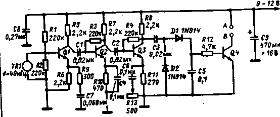
The receiver circuit is shown in Fig.2.

The receiver circuit
The transistors Q1, Q2 and Q3 form a well-known three-stage amplifier, whose task is to increase the received signal strength to the value, when it can be protectivity, and the obtained DC voltage transfer transistor Q4 is in an open state. The total gain of the circuit is regulated by a variable resistor R13, is included in the emitter circuit of transistor Q3. With the collector of this transistor signal is supplied to the rectifier voltage doubler. The DC voltage generated at the capacitor C5, creates an offset at the base of the transistor Q4 through the resistor R12. The receiver Assembly does not differ practically from the transmitter Assembly. As there, the wires connecting the ultrasonic sensor with the scheme should be as short as possible. Ready charge placed in a metal or plastic case.
The introduction of the device
If you follow the picture at the top of Fig. 3.20, the first step in testing the operation of the scheme should be determining how far you can post the transmitter and receiver. Select a place where there is no air flow. The emitter of the transmitter will post at a height of 1 m above the floor, sending it into the open space. Apply power from a temporary source to the receiver. Install the resistor R13 in the position of least resistance, which would correspond to the maximum gain. Connect the DC voltmeter to the terminals Liv. If the amplitude of the ultrasonic waves is high enough, the voltmeter will show the voltage that is almost equal to the supply voltage. Slowly move the receiver from the emitter of the transmitter. With some place the voltmeter starts to jump, sometimes even dropping to zero. Then reduce the distance by 30-60 cm, again making sure that the device works reliably.
When installing ultrasonic alarm should follow some clear guidance.
1. Do not stir it in an area where air conditioning is provided in the blower. Otherwise the alarm will be triggered every time it switches.
2. Do not place near any objects that can wind to get to the beam transmitter.
3. Do not attempt to use the system outdoors or indoors, where it is constantly open Windows and doors.
4. If animals or birds are permanent inhabitants of the territory where you intend to use such alarm, here it is unacceptable.
As mentioned above, it is possible to arrange the transmitter and receiver, the latter will perceive the sound reflected from any solid surface. It can be a stack or door. Clothing reflects poorly, on the contrary, absorbs ultrasound. When someone crosses one of the beams, the alarm will trigger. If under guarded the door, the device reacts when you open it.
The emitter of the transmitter and ultrasonic sensor receiver have a distance of no more than 5 cm from each other, wherein the device is able to "notice" of a person or an object a few inches from him. Wherever you set your creation, don't forget this: should not be adjusted for maximum sensitivity and to use the device in harsh environments. The alarm device combined with the receiver and transmitter
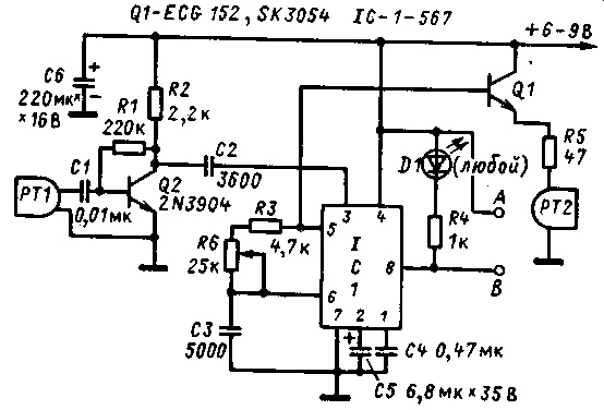
The scheme of the next ultrasonic guard shown in Fig.1. The scheme is unusual in that on the basis of one chip in it assembled generator of the transmitter and that she works as a selective receiver of the reflected signal. This is achieved using the chip 567, containing in itself the source and the receiver.

Fig.1. Diagram of the transceiver
Take a closer look at how the scheme is performing double duty. The waves are perceived piezoceramic sensor, and then amplified by a cascade transistor Q2 they arrive at the terminal 3 chip, and the signal frequency is exactly equal to the one that generates the chip itself. In contrast to the previously described device in that no matter how the frequency may deviate from the original installed.
The operating frequency is determined by the values of the chain of resistors R3 and R6 and the capacitance of the capacitor C3. Is regulated it a variable resistor R6. At given values of parts it can vary in the range of 8 to 25 kHz, and ultimately determined by the piezoelectric transducer. From pin 5 of the chip a square wave signal is supplied to the base of transistor Q1 connected in the circuit with a common collector. As the load of the transistor included a chain of resistor R5 and a low-impedance speaker. When the circuit's input has a sufficient amplitude signal, the led is on, and the terminals a and b are normally closed contacts. In the case where the signal amplitude is reduced or he is quite absent, the output of the circuit goes to open position. Otherwise, this device can be used in any configuration suggested in Fig. 3.20. Frankly, the scheme works better on high frequency sounds than on ultrasound.
The last word on the operating frequency of said applied to the emitter device and the piezoelectric transducer. For those that are in the list of parts used, the frequency ranges from 8 to 16 kHz. If you are not satisfied with such frequency, you just need to pick another pair, since the circuit can operate at frequencies up to 25 kHz. The upper limit is limited only by the capabilities of the chip. But it should not be especially easy, because frequency of 43 kHz it is difficult to pick up the emitter and the piezoelectric transducer.
Complete with two proposed converters scheme works very well at a frequency of 12 kHz. And what she heard. Because hardly anyone dares to argue with her. And mouse, apparently, would prefer some other place than this.
Build schema
The details of the circuit are mounted on a circuit Board of insulating material, and, as they are not so much, the packing density does not affect its functioning. This design is not required to place the piezoelectric transducer and the emitter close to the scheme. But then for each Converter, it is desirable to use a shielded wire. This way you will avoid the occurrence of communication directly between the output and the input of the circuit.
Putting the unit into operation. Having checked up correctness of installation, connect the power scheme. This may be the source voltage V. 6-9 the Slider of the resistor R6 is set to the middle position, you should hear a high pitch squeak. Install the radiator on the Desk or stand in front of him was a space of 3 m. Holding the piezoelectric transducer in hand, "point it at the radiator. The led should light up. Moving away from the piezoelectric transducer from the transducer, notice the place where the led will turn off. This means that you have found the point of maximum sensitivity.
Specify the place where it is convenient to arrange such alarm:
- through the room;
- output;
- on the contrary, wall safe or expensive painting;
- on the passage to the attic or basement;
- in any other place where it may take the robber.
Publication: N. Bolshakov, rf.atnn.ru


