


")

Using a simple ultrasound unit can show the propagation of ultrasound in different media, reflection and refraction of ultrasound at the boundary of two media, the absorption of ultrasound in various substances. Besides, there is an opportunity to show the receipt of oil emulsions, cleaning of contaminated parts, ultrasonic welding, ultrasonic liquid fountain, the biological effects of ultrasonic vibrations.
The manufacture of such installation can be carried out in school workshops by students of senior classes.
Installation for demonstration experiments with ultrasound consists of an electronic oscillator (Fig.1), a quartz Converter of electrical oscillations in the ultrasonic lens and the vessel (Fig.2) for focusing ultrasound. In the power supply is only the power transformer TR1, since the anode circuit of the lamps of the generator are directly fed by an alternating current (without rectifier). This simplification does not adversely affect the operation of the device and at the same time significantly simplifies the circuit and design.
Electronic generator made push-pull circuit of two lamps PSS included in triode scheme (the tube screen grid is connected to the anodes). In the anode circuit of the tubes are connected in the circuit L1C2, which determines the frequency of the generated oscillations, and in the grid circuit is the feedback coil L2. In the cathode circuit included a small resistance R1, to a large extent determines the mode of the lamps.
Fig.1. Schematic diagram of the generator
The high frequency signal from the quartz resonator through the coupling capacitors C4 and C5. The quartz is placed in sealed carreterachina (Fig. 2) and connected with the generator by wires with a length of 1 m.
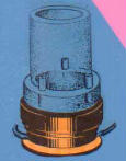
Fig. 2. Lens receptacle and quartzdial
In addition to reviewing the details in the scheme there are capacitors C1 and C3 and also the inductor DR1 through which the anodes anode voltage is supplied. This choke prevents a short circuit of a high frequency signal through the capacitor C1, and the stray capacitance of the power transformer.
The main self-made parts of the generator are the coils L1 and L2, in the form of flat spirals. For their manufacturing it is necessary to cut out a wooden template. From Board width 25 cm are cut two squares that are the cheeks of the template. In the center of each cheek should make the holes for the metal rod with a diameter of 10-15 mm, and in one of the cheeks cut out the hole or the groove width of 3 mm for fixing the output of the coil. A metal rod with both ends cut between the thread and two nuts are placed on the cheeks distance equal to the diameter of winding wire. The manufacturing pattern can be considered complete and start winding coils.
A metal rod with one end clamped in a vise, between cheeks stack the first (inner) loop of wire, then tighten the nuts and continue winding. The coil L1 has 16 turns, and the coil L2-12 turns of copper wire with a diameter of 3 mm. Coils L1 and L2 are made separately, then placed one above the other on the directional pad of the PCB or plastic (Fig. 3). In order to give the coils greater strength in the cross pieces with a hacksaw or a file are cut deeper. To secure the coils one on top should be pressed a second crosspiece (without grooves), and the second to put directly on the plate made of organic glass, Micarta or plastic, attached to the metal chassis of the generator.
Fig. 3
The high frequency choke is wound on a ceramic or plastic frame with a diameter of 30 mm wire marks PELSHO-0.25 mm. Winding is carried out in bulk sections of 100 turns each. Only the throttle has 300-500 turns. In this design uses a self-made power transformer, made in the core of plates of sh-33, the dial thickness 33 mm. grid winding contains 544 coil wire PEL-0,45. Network winding intended for inclusion in the network with a voltage of 127 B. In the case of the mains voltage of 220 V winding I must contain 944 coil wire PEL-0,35. The step-up winding has 2980 turns of wire PEL-0.14 and filament winding lamps - 30 turns of wire PEL-1,0. This transformer can replace the power transformer brand EBW-2 using only the network winding, filament winding tubes and increasing the winding completely, or any power transformer capacity of not less than 70 BA and a step-up winding, thereby providing the load 470 B on the anodes PSS.
Quartzdial is made of bronze on a drawing placed on the rice. 4. In the housing by means of a drill with a diameter of 3 mm are drilled l-shaped hole for the lead wire l, In the case of an inserted rubber ring e, which serves for damping and isolation of quartz. The ring can be cut from conventional rubbers for erasing pencil. Contact ring b is cut from brass foil with a thickness of 0.2 mm. This ring has a petal m for soldering wires. Both wires l and and should have good insulation. Wire and soldered to the mounting flanges O. it is Not recommended to twist the wire together.
Fig.4. Quartzdial
Lens the vessel consists of a cylinder e and ultrasonic lens b (Fig.5). Cylinder arch of the organic glass plate of a thickness of 3 mm on a round wooden pattern with a diameter of 19 mm.
Fig.5. Lens receptacle
The plate is heated over a flame until soft, Flex pattern and glue with vinegar. Cemented cylinder link the thread and leave to dry for two hours. After that sandpaper align end the ends of the cylinder and take the threads. For the manufacture of ultrasonic lenses used needed to make a special device (Fig. 6) of a steel ball with a diameter of 18-22 mm from the ball bearing. The ball should anneal it, heat it to red heat and slowly cooled. Then into the ball drill a hole of 6 mm in diameter and cut an internal thread. For fastening of the ball in the Chuck drill rod from a rod to make the rod threaded on one end.
Fig.6. Fixture
The rod is screwed with a ball gripped in the Chuck of the machine, turn the machine on medium speed and pushing the ball into the plate, organic glass thickness 10 - 12 mm, get the necessary spherical recess. When the ball is being deepened by a distance equal to its radius, the drilling machine is turned off, while pressing the bulb, cool it with water. As a result, in the organic glass plate is obtained spherical recess ultrasonic lenses. From plate with a recess cut with a hacksaw a square with side length 36 mm, line a fine-grained emery paper formed around the annular recess of the ledge and grind off the bottom plate so that the center of deepening the bottom left of thickness 0.2 mm. Then grind to transparency scratched with sandpaper and place and on a lathe, cut the corners so that the spherical recess is left in the center of the plate. From the bottom of the plate it is necessary to make a projection with a height of 3 mm and a diameter of 23.8 mm for the centering of the lens on carreterachina.
Abundantly moistened with vinegar or dichloroethane one of the face ends of the cylinder, stick it on ultrasonic lens so that the Central axis of the cylinder coincides with the axis passing through the center of the lens. After drying in a bonded vessel drill three holes for adjustment screws. Rotate these screws are best with the special screwdriver, made of conventional wire length of 10-12 cm and a diameter of 1.5-2 mm and equipped with a handle made of insulating material. After fabrication of these parts and installation of the generator, you can begin establishing the unit, which usually comes down to the tuning circuit L1C2 in resonance with the natural frequency of quartz. Quartz plate in (Fig.4) should be washed with soap in running water and dried. Contact ring b top sanded to a Shine. Accurately superimposed quartz plate on top of the contact ring and dropping a few drops of transformer oil at the edges of the plate, tighten the cap d, so that it is pressed quartz plate. To display the ultrasonic vibration of the recesses a and g on the cover is filled with transformer oil or kerosene. After power-minute warm-up and rotate the knob to achieve resonance between the oscillations of the oscillator quartz plate. At the time of resonance is observed maximum swelling of the liquid poured into the recess on the lid. After setting the generator can begin to demonstration experiments.
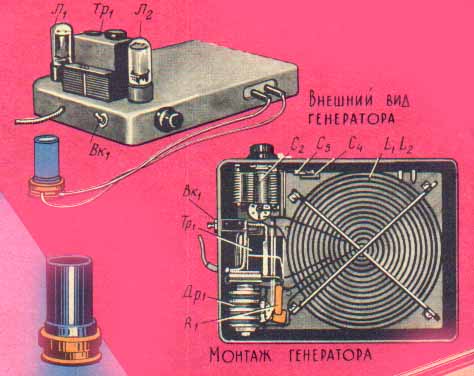
The design of the generator.
One of the most effective demonstrations, is to get a fountain of liquid under the action of ultrasonic vibrations. In order to get the fountain fluid, you need "lens" vessel to be placed on top of cartegories so that between the bottom of the "lens" of the vessel and the quartz plate was not formed clusters of air bubbles. Then pour in a lens receptacle ordinary drinking water and a minute after turning on the generator at the water surface will ultrasonic fountain. The height of the fountain can be changed by means of trimmer screws, pre-adjusting the generator by means of the capacitor C2. When properly configured, the entire system can be obtained a water fountain with a height of 30-40 cm (Fig.7).
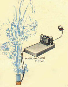
Fig.7. Ultrasonic fountain.
Simultaneously with the appearance of the fountain water mist occurs, which is the result of the cavitation process, accompanied by a characteristic hiss. If "lens" vessel instead of water to pour transformer oil, the fountain height increases markedly. Continuous observation of the fountain may be performed until until the liquid level in "lens" of the vessel is reduced to 20 mm. For long-term observations of the fountain should protect him a glass tube B, on the inner walls of which gushing fluid can drain back.
Under the influence of ultrasonic vibrations on the liquid in it the formation of microscopic bubbles (cavitation phenomenon), which is accompanied by a significant increase in pressure at the place of generation of bubbles. This phenomenon leads to the destruction of particles of matter or living organisms in the liquid. If "in lens" a container of water to put a little fish or Daphnia, then after 1-2 minutes of exposure to ultrasound, they will die. Projection "lens" of the vessel with water on the screen gives you the opportunity to consistently observe all the process of that experience in a large audience (Fig.8).
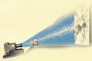
Fig.8. Biological effects of ultrasonic vibrations.
With the described device it is possible to demonstrate the use of ultrasound for cleaning small parts from contamination. For this purpose in the base of the fountain fluid, place a small item (a gear from a clock, a piece of metal, etc.), liberally lubricated with grease. The fountain will be greatly reduced and may stop altogether, but polluted detail gradually cleared. It should be noted that cleaning of parts ultrasound requires the use of more powerful generators, so clean all contaminated item in a short period of time and not need to be limited to remove several teeth.
Using the cavitation phenomenon, you can get an oil emulsion. For this "lens" is a vessel filled with water and top with a bit of transformer oil. To avoid splashing of the emulsion, you need a lens with the contents of the vessel to cover the glass. The inclusion of the generator forms a fountain of water and oil. After 1-2 min. of irradiation of the lens in the vessel forms a stable emulsion milky color.
It is known that the propagation of ultrasonic vibrations in the water can be made visible and to demonstrate some properties of ultrasound. This requires a bathtub with transparent and flat bottom and large sizes, with a depth of not less than 5-6 cm tub is placed over the hole in the sample table, so that you can cover all transparent bottom bottom. For lighting it is good to use sixvolt automotive light bulb as a point source of light for projection of the processes studied at the ceiling of the audience (Fig.9).
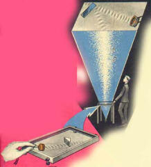
Fig.9. Refraction and reflection of ultrasonic waves.
You can use ordinary light bulb with a small capacity. In the bath, pour water so that the quartz plate in carreterachina vertical positioning was completely immersed in it. You can then turn on the generator and, by turning quartzdial vertical to inclined, to observe the propagation of the ultrasonic beam in the projection on the ceiling of the audience. Quartzdial you can hold up to him the wires l and C, or previously to fix in a special holder, which allows you to smoothly change respectively the angles of incidence of the ultrasonic beam in the vertical and horizontal planes. The ultrasound beam is observed as bright spots along the propagation of ultrasonic vibrations in the water. Placing on the path of propagation of the ultrasonic beam is something in the way, you can observe the reflection and refraction of the beam.
Describes the installation and allows other experiments, the nature of which depends on the study programme and classroom equipment. As the load generator, you can include a plate made of barium titanate and generally any of the plate having the piezoelectric effect at frequencies from 0.5 MHz to 4.5 MHz. In the presence of plates on other frequencies you want to change the number of turns in the coils (increase for frequencies below 0.5 MHz and decrease for frequencies higher than 4.5 MHz). Alteration in the oscillating circuit and the feedback coil at the frequency of 15 kHz can be inserted in place of any quartz magnetostrictive transmitter power not exceeding 60 VA
Author: V. Krasnik; Publication: N. Bolshakov, rf.atnn.ru