


")

Despite the wide-branched network of rescue services on the water, still there are accidents, usually caused by a violation of the rules of conduct on the water. One of the main challenges facing rescue workers is timely assistance to victims. How quickly will found people in distress, or just drowned, depends will save him or not.
The article describes the set of devices intended to signal a sinking swimmer. This kit is required when carrying out works associated with a short-term dip at a shallow depth without scuba gear. The sonar detector is indispensable during the competition divers on the duration of stay under water. The idea of signaling with the assistance of electronic devices on excessively long, and therefore dangerous to life, stay under water deserves the attention of radio Amateurs. A sensor responsive to a long stay at a depth of 1-2 m below the water is not universal, since an accident can occur at smaller depth. Ought to construct a sensor responsive to cessation of breathing or heartbeat. Many still unsolved problems in the application of electronics for snorkeling, and in particular for establishing reliable communication under water. This opens space for creativity of radio fans, which should help the rescuers in their noble and difficult task.
Hydroacoustic equipment of the automatic signaling of a drowning man consists of a compact automatic transmitters and one "duty" of the receiver. The transmitters are fixed on the body of the swimmers, and the receiver is on rescue post directly on the water. When receiving distress signals from any transmitter to rescue post automatically turns on the light and sound alarm.
The range of the instrument is about 200 m.
Transmitter
Transmitter, block diagram of which is placed in Fig. 1, a schematic diagram is in Fig. 2, consists of an immersion sensor, time relay and the generator of ultrasonic vibrations with piezoelectric transducer. The operating frequency of the transmitter 53 kHz.
Fig.1
With the aim of increasing the reliability and efficiency of the transmitter integrating a power is exercised by the sensor pins dip, which is adjusted so that the circuit when immersed to a depth of more than 0.2-0.5 m.
Fig.2
Time relay eliminates the possibility of false signals when diving swimmers and includes transmitter only through 55-60 seconds after activation of the sensor immersion. This exposure time is selected based on the fact that a trained swimmer can hold his breath under water for about one minute: case of human stay under water longer than one minute can be regarded as life-threatening. If in practice and will meet the cases where a diver can remain under water for longer than one minute, then, first of all, after lifting the swimmer to a depth less than the border triggering sensor immersion alarm will go off, and, secondly, in the receiver there is additionally a timer, the shutter speed can be adjusted depending on the need within wide limits.
For radiation and reception of ultrasonic oscillations in the transmitter and in the receiver applied piezoceramic transducers of barium titanate sensitivity 3-10 mV/bar having the shape of a hollow cylinder with an outer diameter of 30 mm, an inner diameter of 26 mm and a height of 28 mm. the Electroacoustic efficiency of such converters is about 25%.
Cylindrical transducers allows to obtain an Omni-directional receiver and transmitter, a sufficiently low height of the transducer to the length of the working wave approximates the directional characteristics of the spherical. Still, converters cylindrical shape of the spatial characteristics of the radiation (reception) has a zone of low intensity (sensitivity) signals. Although the probability of coincidence of areas of low intensity of transmitters with the area of low sensitivity of the receiver is small, these zones it is desirable not to have. To obtain in the space of a full spherical and uniform characteristics of the radiation (reception) more efficient use in the apparatus of converters spherical shape.
The generator of ultrasonic vibrations and the time relay is made of two transistors T1 and T2 of type U-13 and U-401. The first of them collected time relay and the second - the actual generator. The generator is assembled on the circuit with inductive feedback.
As a power source in the transmitter uses two batteries type D-0,06 connected in series. When immersed to a depth of less than 0.2-0.5 m transmitter of electrical energy does not consume; if you are at a greater depth when the time relay, the consumption current is 4.0 mA. In the emission mode, the transmitter consumes a supply current of 3.0 mA, so practically it can be considered that the duration of the sources litany during one cycle is determined by the time of their discharge. Output electrical power of the transmitter is 6.0 mW acoustic power is about 2 mW.
Location details transmitter is depicted in figure 4.
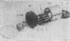
Fig.4
The transmitter is mounted inside the housing of the piezoelectric transducer on a rectangular laminated bakelite circuit Board having dimensions 15x22 mm. the Transistor T2 is taken with a gain of at least 60. Transformer Tp1 is made on a ferrite ring (f-600) with an outer diameter of 8 mm. Windings I and II contain, respectively, 70 and 9 turns of wire PELSHO 0,17. For the purpose of obtaining the smallest dimensions of the capacitor C1 is assembled from 12 parallel connected capacitors type AMY 10 UF 3B.
The bottom end of the inverter (PCU) adhesive 88 is fixed in the groove laminated bakelite figural lid. In the housing cover is fitted with a sealed battery compartment. Batteries should be replaced through the bottom of the cover, mounted on six screws. The bottom sealing is performed by a round rubber gasket cross section 2x2 mm diameter of 20 mm.
Schematic drawing of the immersion sensor is given in Fig. 5. Contact group (K) sensor immersion reinforced on the inner side of the top cover (VC) of the Converter. Perceiving the sensor element immersion is the bearing pin (1), made in the form of a mushroom.
Fig.5
The diameter of the top platform equals 10 mm. Top of the lid and the reference pin by the adhesive 88 is glued elastic rubber (2) thickness 0.2-0.3 mm. immersion transmitter to a depth of 0.2-0.5 m vertical pin under the pressure of the water, until it stops moving in the limiter switches the contacts. Adjustment of the depth gauge is made with the help of cargo, equal to the force of pressure of the water column with a height of 0.2-0.5 m (about 40 g).
The frequency of oscillation is determined by the inductance of the primary winding of the transformer Tri capacitance of the piezoceramic transducer. Configuring the transmitter is on frequency to the resonance frequency of the transducer by changing the number of turns of the primary winding of the transformer. Configure the transmitter by connecting in parallel the inverter additional capacitor is undesirable because it results in the unnecessary loss of output power of the transmitter. Exposure time relay is controlled by changing the capacitance of the capacitor C1.
The question of the most efficient placement of the transmitter on bathing a person of great importance both from the point of view of shielding unwanted signals from the transmitter in the human body, and from the point of view of ensuring freedom of movements of the swimmer in the water.
As experience has shown, the most convenient option of placing the transmitter on bathing a person should be mount on the swim cap-specially provided rubber "pocket". In connection with low weight (50 g in air and 22 g in water) this mounting method does not cause discomfort.
Receiver
Propagating from the transmitter on water ultrasonic vibrations are perceived piezoceramic transducer, amplified receiver-amplifier circuit and carry out the activation of the alert signal.
Schematic diagram of the receiver shown in Fig. 3. He collected eight transistors on a kind of the superhet circuit with a grounded emitter and is designed to operate at a fixed frequency of 53 kHz. Nominal voltage - 15 V (four batteries KBS-L-0,5); by reducing the voltage to 11 In the performance of the receiver is fully preserved.
(click to enlarge)
Fig. 3. A capacitor C17 is connected to a collector of the transistor T8.
Current consumption in standby mode of about 17-20 mA; includes mode preliminary indicator about 105 mA, and in the mode of operation of the alarm - no more than 300 mA.
The gain of the receiver voltage equal 6-9-105. The sensitivity, defined by a minimum value of the signal on the base of the first transistor, wherein the relay P1 is equal to 1 mV.
The RF amplifier consists of three stages collected in the transistors T1, T2, T3. Converter control panel together with the primary winding of the transformer Tp1 circuit is tuned to resonance at the frequency of 53 kHz. Interstage matching transformers TP2, and TP3 are also resonant load and increase the selectivity of the receiver.
To obtain maximum gain and reduce the possibility of self-excitation cascades RF amplification the second and third stages, collected by cascadei scheme with parallel feeding. Enhanced ultrasonic vibrations with a frequency of the local oscillator with the secondary winding of the transformer TP3 fed to the mixer, assembled on the transistor T4. The heterodyne receiver is assembled on the transistor T8 in the same pattern as that of the oscillator of the transmitter. Low-frequency oscillations representing the frequency difference between the main signal and the local oscillator are highlighted in the winding I of the transformer Tp4 are amplified by the amplifier stage bass, performed at the transistor T5. After rectification (diode D1), the voltage signal is fed to the amplifier decent current (transistor T6) with a highly sensitive polarized relays P1 in the circuit of the collector.
Upon receipt of the signal relay P1. Through the contacts of this relay is powered at a preliminary indicator light L1, to one pole of the call (SV) alarm and simultaneously removed the negative supply voltage from capacitor C16 and from the base to open this transistor T7 timer. The contacts of the relay R2 are open. The capacitor C16 is running low on resistance R24, and after a while the current of the transistor T7 is reduced so that the armature of the relay R2 will throw the relay contacts and the positive power source connected to the second output of the call, activating the alarm. The dwell time relay time can vary from 0 to 60 sec. by using a variable resistance R24 displayed on the front panel of the receiver.
In good receiver when lightly rubbing your finger across the surface of the Converter lights up light L1 and the audible alarm will sound.
The receiver is mounted on two laminated bakelite circuit boards mounted on the chassis and on the front panel of the device, rigidly attached to the chassis. The chassis is inserted into a metal casing having dimensions HH mm, which reinforced carry handle of the device and locks to secure the chassis within the housing. Installation and location of parts receiver are clearly visible in Fig. 6.
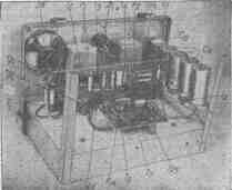
Fig.6
On the front panel of the receiver is displayed: switch P1 the light L1, the R24 potentiometer knob with scale installation time-delay and a connector for connecting a coaxial cable to the sonar transducer.
Relays P1 and P2 applied type RP-5, two-position dominated. The resistance of the relay coils 6000 ohms.
Hydroacoustic transmitter receiver mounted between two brass caps, which are pulled together by three pins. Sealing the internal cavity of the Converter is performed rubber gaskets in the grooves. In one of the covers has a seal with a rubber seal through which the cable type PK-1 from the receiver.
Winding data transformers are given in table. 1.
Designation scheme
The number of turns of the windings
Mark and wire diameter
Core type
I
II
III
TP1
250
-
-
PEL 0, 1
Carbonyl type SB-1
-
100
-
PEL 0, 1
TP2
520
-
-
PEL 0, 1
Carbonyl type SB-1
Winding I is wound over the winding II
-
60
-
PEL 0,12
TP3
500
-
-
PEL 0, 1
"
-
50
-
PEL 0,12
TP4
2000
-
-
PEL 0, 1
Ferrite, W-shaped uH=1000 S = 0,'8 cm2
-
200
-
PEL 0.18
TP5
350
-
-
PEL of 0.1
Carbonyl type SB-1 Winding I is wound on top of the windings II and III
-
40
-
PEL 0,15
-
-
50
PEL 0,15
When mounting the receiver, special attention should be paid to the placement of the amplifier stage RF and lo. Transformers should be placed from each other at a distance of not less than 30 mm, and so that their axes of symmetry were located at an angle of 90°; the local oscillator is preferably mounted on a separate Board together with the Executive part of the receiver.
After checking the correct installation of the receiver is powered up and verified modes of transistors DC (see table 2).
Transistors
IR= In
IC,mA
IR~, mV
in
Co, mA
T1
0,5-1
0,4 - 0,5
4-9
40-50
1-2
T2
2,2
2-2,4
3-6
40-50
3-5
T3
3, 1
0,4-1
150-270
40-50
3-5
T4
14,6
0,8-1
0.6 to 1.5 in
30-40
5-10
T5
5,5
10
1.8-2
30-40
5-10
T6
14
0.15 to 0.2
-
40-50
3-5
T7
3
2
-
40-50
3-5
T8
1,5
0,1
of 0.65 in
30-40
10-15
Notes:
1. The modes of the transistors are given in the Uвх=1-2 mV.
2. Modes of transistors DC voltage and current measured by the device TT, modes DC voltage measured tube voltmeter type MVL-2M.
After that, tune the RF amplifier. Why disable the local oscillator and to the input of the receiver from the generator of standard signals through capacitor of 0.05 - 0.1 µf serves unmodulated oscillations with a frequency of 53 kHz; reinforced high-frequency voltage tube is measured with a voltmeter at the collector of transistor T3. When you turn off the signal from the receiver input voltmeter should show the voltage noise of the receiver. The magnitude of these noise to the input, should not exceed 0.01 µv for the configured receiver (with short-circuited). If when you turn off the signal to the voltmeter shows the voltage significantly above the noise level, it indicates the initiation stages of RF amplification. To address this should be slightly spread apart transformers TP2, TP3 and, in some cases, helps to change the ends of the secondary windings of these transformers.
Then you need to set the resonance circuits of transformers Tp1, Tp2, TP3 and changing the values of capacitors C3 and C8 or the selection of the numbers of turns of the primary windings.
In the last instance, you can set loop, formed by the hydro-acoustic Converter and the primary winding of the transformer Tp1. In this case, the signal at the receiver input is perceived directly by the inverter from the control panel of an inductance coil connected to the output of the GSS and installed at a distance of 10 - 15 cm from the control panel. For an inductor with GHS signal voltage of about 1 V. the input circuit at resonance is achieved by changing the number of turns of the winding I or contour-parallel connection of capacitors. Resonance is determined by the maximum voltmeter reading. The receiver sensitivity after setting the input circuit should be increased in 1,5-2 times.
Connected to the heterodyne scheme is configured on the frequency counter to the frequency 51-51,5 kHz by changing the number of turns of the winding I of the transformer Tp5 and trimming the core.
The operation of the mixer amplifier and WOOFER is verified when applied to the receiver input frequency 53 kHz from the GSS. The greatest increase and better transmission of low frequency signals is achieved by selection bias on the base of transistor T4 through resistors R10 and R12.
P1 relay actuation part of the receiver must operate at the voltage on the base of the transistor T6 minus 0.1 to 0.2 V, the collector current in this case is $ 0.15 to 0.2 mA; when you install the electromagnetic relay with a more low-resistance windings collector current can increase up to 8-10 mA.
After configuring the transmitter and receiver separately checks the operation of all devices in the water.
Authors: A. Davydov, V. Davydov; Publication: N. Bolshakov, rf.atnn.ru