


")

Incandescent bulbs are cheap though, but consume a lot of electricity, so many countries waive their production (USA, Western Europe). Instead they are being replaced by compact fluorescent lamps fluorescent light (energy saving), their spin in the same cartridges E27, incandescent lamps. However, they are 15-30 times more expensive, but in 6-8 times longer and 4 times consume less electricity, which determines their fate. The market is full of variety of such lamps, mainly in China. One of such lamps, firms DELUX, shown in the photo.
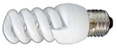
Her power 26 W -220 V, and the power supply, also called electronic ballast, located on the circuit Board dimensions 48x48 mm (Fig.1) and located in the basement of this lamp.
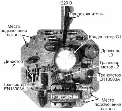
The radioactive elements placed on the circuit Board mounted Assembly, without the use of the CHIP elements. Schematic diagram drawn by the author from examination of the circuit Board shown in Fig.2.
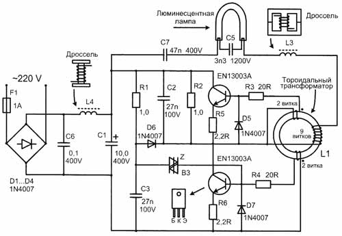
First, it is pertinent to recall the principle of ignition of fluorescent lamps, including when using electronic ballasts. For ignition of fluorescent lamps it is necessary to preheat the filament and applying a voltage of 500…1000, i.e. considerably more than the power supply voltage. The magnitude of the ignition voltage is directly proportional to the length of the glass envelope of a fluorescent lamp. Naturally, for a short compact lamps it less, and for long tubular lamps - more. After ignition the lamp dramatically reduces its resistance, and therefore, it is necessary to use a current limiter to prevent a short circuit in the chain. Circuit of electronic ballast for compact fluorescent lamp is a push-pull half-bridge voltage Converter. Initially the supply voltage by 2-half-cycle of the bridge rectified to a DC voltage of 300…310 V.
Run the Converter provides symmetrical dinistor, scheme Z, it opens, when, turning on the mains, the voltage at the points of connection exceeds the threshold. When opening, using a dinistor passes a pulse to the base scheme of the transistor, and the inverter is started. Further half-bridge push-pull Converter, the active elements of which are two transistor n-p-n, converts the DC voltage of 300…310, in a high-frequency voltage, which can significantly reduce the size of the power supply.
Load of the Converter and its control element is a toroidal transformer (marked in the diagram L1) with three windings, two control windings (each two turns) and one working (9 turns). Transistor switches are opened from antiphase positive pulses from windings of governors. For this control winding is included in bases of transistors antiphase (Fig.2 start windings indicated by dots). Negative surges with these windings are extinguished diodes D5, D7. The opening of each key causes the tip of pulses in two opposite windings, including in the operating coil. The AC voltage to the operating winding is fed to the fluorescent lamp through a serial circuit consisting of: L3 - filament lamps-C5 (3.3 nF 1200) - filament bulbs - C7 (47 nF/400 V). The values of the inductances and capacitances of the circuit are chosen so that in it there is a voltage resonance at a fixed frequency Converter.
When the resonance voltage in a series circuit, inductive and capacitive impedance are equal, the current in the circuit is maximum, and the voltage on the reactive elements L and C can greatly exceed the applied voltage. The voltage drop on C5, in this series resonant circuit, 14 times more than the C7, since the capacitance C5 is 14 times smaller and its capacitive reactance is 14 times more. Therefore, prior to ignition of a fluorescent lamp maximum current in the resonant circuit both heats the filament, and a large resonant capacitor voltage C5 (3.3 nF/1200) in parallel to the lamp that lights the lamp. Note the maximum allowable voltage on the capacitors C5=1200 and S7= 400 V. These values are chosen for a reason. At resonance the voltage on C5 reaches about 1 kV and it needs to withstand.
Lighted lamp dramatically reduces its resistance and blocks (short-circuits) the capacitor C5. With the resonant circuit eliminates the capacitance C5, and the voltage resonance circuit is stopped, but the burning lamp continues to glow, and the inductor L2 self-inductance limits the current in a lighted lamp. In this case, the Converter continues to operate in automatic mode without changing its frequency since the launch. The entire ignition process lasts less than 1 s. it Should be noted that the fluorescent lamp all the time is an alternating voltage. It's better than standing, as it provides uniform wear of the emission ability of the filaments and thus increases its service life. When powered lamps from DC its service life is reduced by 50%, so the DC voltage at the discharge lamp is not available.
The purpose of transducer elements:
Types of radioactive elements are indicated on the schematic diagram (Fig.2).
1. EN13003A - transistor switches (on the wiring harness manufacturers for some reason they are not marked). It is a bipolar high-voltage medium power transistors, n-p-n conductivity, the case TO-126, their analogues MJE13003 or CTA (400V, 1.5 A, pulse 3 (A), and CTA (1500 V; 8 A; case TA), but in size they more than. In any case, it is necessary to set the outputs of the energy buffering operation, as different manufacturers may be different sequences, even in one and the same analogue.
2. Toroidal ferrite transformer, designated by the manufacturer L1, ring sizes 11x6x4,5, probable magnetic permeability of 2000, has 3 windings, two of them in 2 turns and one 9 turns.
3. All diodes D1-D7 of the same type 1N4007 (1000V, 1A), including the diodes D1-D4 rectifier bridge D5, D7 - extinguish negative emissions control pulse, a D6 - shares the power supplies.
4. Chain R1СЗ provides the delayed start of the Converter to "soft start" and not assumptions inrush current.
5. Symmetrical dinistor Z type DB3 Uзс.max=32 V; Uoc=5 V; Uнеотп.and.max=5 V) provides initial startup of the Converter.
6. R3, R4, R5, R6 - limiting resistors.
7. C2, R2 - damping elements for damping emissions transistor switch in its closure.
8. The inductor L1 consists of two glued together W-shaped ferrite halves. First, the choke is involved in the stress response (together with C5 and C7) for ignition of the lamp after its ignition extinguishes the inductance current in the fluorescent lamp circuit, as a lighted lamp dramatically reduces its resistance.
9. C5 (3.3 nF/1200), C7 (47 nF/400 V) - link capacitors fluorescent lamps involved in the ignition (via the stress response), and after ignition C7 supports glow.
10. C1 is a smoothing electrolytic capacitor.
11. Choke with ferrite core L4 and the capacitor C6 constitute a rejection filter that does not pass the impulse noise Converter in the supply grid.
12. F1 - mini-fuse in the glass body 1 And is outside of the circuit Board.
Repair
Before repairing electronic ballast, you need to get to its circuit Board, it is enough with a knife to separate two parts of the cap. When repair fee under tension, be careful, as the radioelements are under the phase voltage!
Burnout (burnout) makalnyh spirals fluorescent lamps, with electronic ballast remains intact. This is a typical malfunction. To restore the spiral is impossible, and glass luminescent bulb such lamps are not sold separately. What's the solution? Or adjust defective ballast to a 20-watt lamp having a straight glass tube, instead of its native throttle (the lamp will operate reliably and without rumble) or to use elements of the Board as spares. Hence the recommendation: buy the same type compact fluorescent lamps - will be easier to repair.
Cracks in soldering circuit boards. The reason for their appearance - the periodic heating and subsequent, after the shutdown, the cooling of the joint. Heated up the soldering of elements that are heated (spiral fluorescent lamp, transistor switches). Such cracks may occur after several years of operation, i.e. after repeated heating and cooling of the joint. Eliminated the fault re-soldering cracked.
The damage of some radioactive elements. Individual components can be damaged from cracks in the soldering, and power surges in the mains supply. Although in the scheme and there is a fuse, but it will not protect the components from voltage surges, as it could make the varistor. The fuse will burn from the breakdown of radioactive elements. Definitely the weakest point of all the components of this device are transistors.
Author: N. P. Vlasyuk, Kyiv; Publication: www.cxem.net