The device is a mechanical on/off switch powerful load (up to 6 A, 220 V) depending on the light sensitive element. The instrument has a threshold control on/off. Small size and weight, high reliability, ease of manufacture makes twilight switch is extremely effective in order management automation your electrical appliances and energy saving. In addition, the device is not gives interference on the mains.
To assemble such a device can set MASTER KIT NK005.
On the street, in the country or in a city apartment, it is often necessary control of electrical devices depending on the time of day (in other words light from illumination of the object). How convenient, when with the coming of dusk automatically turns on the light bulb of the street, the front or the dark stairs the entrance, and in the morning turns off; in the country will turn on the heating element in Your the shower or run the pump, reserving the water for a morning watering. Except automation of the processes of commutation it is necessary to remind about the possibility significant savings of energy during such a time of dividing the work appliances. All these functions can be placed on light-sensitive automatic on/off load, which is called twilight switch.
Specifications
- The voltage, V..............................220
- The power of the connected load, W.......1300
- The dimensions of the PCB, mm......................61x36
Such devices are widely spread. There are not a dozen various circuit design, a very simple and very complex systems with microprocessor control. Therefore, before developers MASTER KIT the task was to make as simple, modern (relatively element base), cheap, compact, but at the same time possessing the attractive consumer properties and reliability of the device.
Description of the module
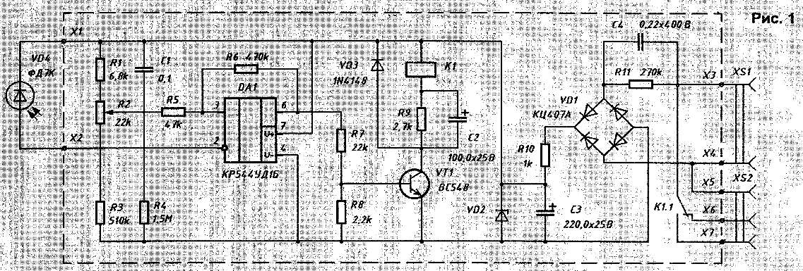
A circuit diagram of a twilight switch shown in Fig.1.

(click to enlarge)
Twilight switch consists of a photo detector VD1 (photodiode in reverse enable - analogue of photoresistance), Schmitt trigger, transistor switch, electromagnetic relay and power source. The Schmitt trigger is made on the operational amplifier DA1, covered by positive feedback through resistor R6. The non-inverting input DA1 through a resistor R5 is connected to the engine the variable resistor R2, which adjusts the switching threshold. The output voltage of the Schmitt trigger through the resistor R7 controls the operation of the electronic key, which is made on transistor VT1. In the collector circuit VT1, through the parallel connected resistor R9 and the capacitor C2 included the winding of the electromagnetic relay K1, contact the group K1.1 which closes/opens (depending on connection points load, 5-6 point on the circuit, 5-7 on the switch opening respectively) the voltage supply to the load connected via the connector XS2. When circuit VT1 electronic key, the capacitor C2 is charged through the relay coil K1, creates a current pulse sufficient to attract the armature of this relay.
After capacitor charge relay anchor is held in a smaller current flowing through the resistor R9, which makes the device more economical from the point of view of current consumption. The VD1 diode protects the transistor VT2 from pulsed breakdown at the time of the start relay K1. Power source twilight switch consists of a resistor R10, the Zener diode VD2 voltage stabilization In 24, capacitor C3 and diode bridge VD3. To the diode bridge through the quenching resistor R11 and capacitor C4, connected in parallel, supplied mains voltage 220 V (connector XS2). When disconnect power to the unit, the capacitor C4 discharges through resistor R11, which reduces the risk of electric shock.
If necessary, switching the load with a current consumption of more than 6 And the relay K1 can be replaced by more high-current (with the same circuit parameters the primary winding) or use a relay K1 to include another, more powerful relay.
Many will ask: "why as a switching element is selected electromagnetic relays? Because you could in good conscience use the thyristor?" The answer to this question is very obvious.
First, the relay may provide absolute electrical isolation of the light machine and dial-up equipment.
Secondly, since the thyristor is a semiconductor multilayer the structure, in the open state, the voltage drop is about 2 In that when the current is 6 And is 12 watts power dissipation.
And now you can compare the dimensions of the electromagnetic relay and thyristor with heat sink. Greatly reduce power dissipation can instead of using thyristor modern FETs with low on resistance drain-source outdoor condition. In this case we have minimal power dissipation, but do not have galvanic isolation of the twilight switch and switching devices.
Attention! This device has a transformerless, so touch to open the conductive areas of the Board life threatening.
Design
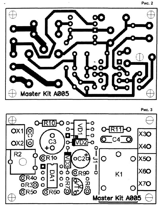
Appearance twilight switch shown in the photo, the printed circuit Board in Fig. 2 (scale 2:1), the arrangement of elements in Fig. 3.

Structurally, the twilight switch is on the circuit Board from foil fiberglass. For fixing PCB mounting reserved screw holes 2.5 mm.
The design of the device allows you to mount the device in the housing BOX-G025 under the clamp the edges of the boards with screws.
For easy connection of supply voltage, load and photodiode on the Board reserved seats under the terminal screw terminals (paired - point X1 and x2, X3 and X4; triple - point X5, X6, X7).
Attention! Because the device has no galvanic isolation from electrical the AC voltage, it is necessary to carefully isolate the twilight the switch from moisture and away from possible contact with live conductors.
In the absence of galvanic isolation from the AC voltage, it is recommended to install the diode inside the housing of a light machine gun will make the appliance is electrically safe maximum.
Properly integrated twilight switch requires no configuration. However, before for the first time, check your installation. Attention! Especially carefully check up correctness of installation of the transistor, IC, diode, Zener diode, the diode bridge and an electrolytic capacitor.
Conclusion
MASTER KEITH is preparing to release a new version of a set NK005, which consists of PCB enclosure BOX-G025, all required components, manuals the Assembly and setup. Additional information can be obtained to get on the website www.masterkit.ru
Author: G. Ganichev, Moscow.


