In wiring the lighting of long corridors, flights of stairs, entrances, long sheds and other places where need to turn on and off the light of the two (input and output, the beginning and the end of the corridor) and more than places, normally apply the so-called corridor switches. Install them in different parts of the corridor. The scheme is known to any electrician, and to change the status of lighting (on, off) the switch needs to be set to the opposite the former position. This scheme requires the strip to the switches have three wires instead of two, and that's only if you manage the lighting from two places. Case management must be greater than three, four, not only the wiring is complicated geometric profession, but and complicated the management process itself, as has already not need to choose between the two, and of the three, four positions of the handle switch.
In this case, a good solution may be an electronic switch on the basis of the D-flip-flop whose state can be changed by button. Moreover, the number of buttons completely unlimited. The buttons are connected in parallel to one low-power two-wire line, anywhere and in any quantity. Pressing any of these buttons changes the state of the lights (on, off).
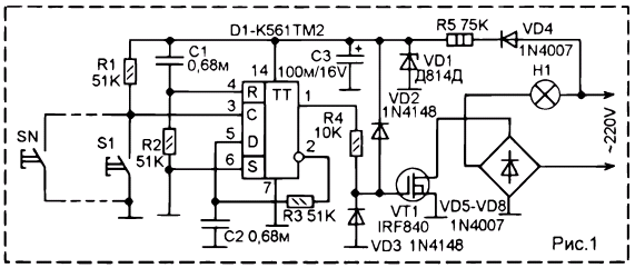
Figure 1 shows a diagram of the first embodiment corridor switch - single lamp.

Fig. 1
Line voltage is supplied to the circuit. At power-up (for example, turn on the breaker in the panel) on the IC D1 receives voltage power equal to 12 V. This voltage is generated using a simple transformerless DC source. Line voltage is rectified diode VD4 and one of the rectifier bridge diodes VD5...VD8. Resistor R5 with the Zener diode VD1 forms parametric stabilizer, a reducing and stabilizing the voltage at level 12 V. the Capacitor C3 smoothes pulsations. When power is supplied to charge C1 through R2 generates a pulse that sets flip-flop to the zero state. Voltage on the valve VT1, as well zero, the transistor is closed and the lamp H1 is not lit.
To light the bulb you need to change the state of the D-flip-flop to the opposite. For do this, press and release the S1 button (or any of the number S1-SN). So create the input. With the momentum that sets the trigger to the state which has at its input D. since D is connected to the inverse output, it level the opposite of what is applied to the gate field-effect transistor. In the level of the direct output D1 changes with each press of the button. When the true output unit D1 the VT1 transistor opens and turn on the lamp.
The trigger on the chip works very quickly, and any button even slightly, but rattles. Therefore, when you click the trigger can be installed in any random position, as one press gives not only one main pulse, but a lot of short pulses from rattling. Now to suppress from crashing bounce introduced chain C2-R3. It does not allow the state of the input D of the flip-flop to change too quickly. Therefore, how much spurious pulses are not generated rattly button, but if they shorter than the time constant of this circuit, the state change will be only one. Resistor R4 unloads the trigger output from the influence of the charging current gate capacitance powerful field of the transistor. Diodes VD2 and VD3 accelerate discharge gate capacitance and suppress voltage spikes which may be on gate capacitance.
The scheme in figure 1 controls only single bulb (or one lighting circuit, consisting of several lamps). This is not always convenient in cases with very long length space is desirable make two groups of lamps, which would be controlled from anywhere premise, therefore setting button in these points
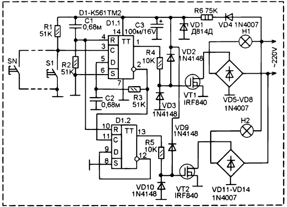
Figure 2 shows the scheme corridor switch, working with two lamps (or two the lighting circuits consisting of several lamps). Here we use the second the trigger circuit KTM, in which the first scheme is not employed. It is connected in series to the first trigger forming a two-digit binary counter different from "typical" only in the presence of the delay circuit R3-C2 in the first trigger link. Now, the state of the outputs of the triggers will vary respectively binary code.

Fig. 2
At power-up both triggers are set to the zero state to this was the input R of the second flip-flop is connected to the same input of the first. Now chain C1-R2 acts on both triggers, setting them at power up.
With the first click button in one state sets the trigger D1.1-enabled lamp N1. If you press the trigger condition D1.1 will change and lamp H1 lights off, but will the status change of the second flip-flop D1.2 - on its direct output is set to logical unit and opens the transistor VT2, which will include lamp H2.
With the third push of a button binary counter goes into a state of "3" unit will be on direct outputs of both triggers and you will burn both lamps. And with the fourth clicking both lamps will go out.
More differences in the schema no.
Using transistor IRF840 and diodes 1N4007 in rectifier bridges, power of each lamp or each circuit lighting, if it consists of several lamps must not exceed 200 watts. If load more powerful, it will require replacement of 1N4007 diodes in the bridges on the diodes corresponding load capacity. Plus, field-effect transistors you need to be put on the radiators. Generally, in IRF840 this scheme can manage loads of up to 2000 watts, but only with radiators, and when the load power up to 200W due low resistance in the open state on the falling output transistors very small, and therefore the radiators when working with loads up to 200 watts to them not required.
The 1N4148 diodes you can substitute almost any diodes, for example, KD521, KD522 CD, CD.
The 1N4007 diodes can replace any rectifier diodes, a voltage lower than 400 V and current according to the power load. For example, if the load is not more than 120 watts use diodes CD.
Zener DD can be replaced by a Zener diode 11...13 V. Preferably use a Zener diode average power or in a metal case. In General keep in mind that upon breakdown of the Zener diode 220 To go on the entire circuit (the chip, the gates of transistors) that it almost completely destroy, therefore, the reliability of the Zener diode is of great importance.
Author: The San'kov, E. M.


