The proposed controller allows you remotely, just by clapping their hands, to turn on and off a lamp or other lamp with bulb and choose from three levels of brightness. Change the brightness, and including the inclusion is smooth, which significantly prolongs the service life of lamps.
Clapping is selected as control signal for the reason that acoustic characteristics it differs markedly from speech or music. Of course, we cannot exclude the operation of the controller and the other sharp sounds (explosions fireworks, car horns or exhaust), so you should not use this the device out well Soundproofed room.
Consumed by the dimmer power does not exceed 4 VA and depends mainly on no-load current of the primary winding of the power transformer. This is several times less the amount consumed in sleep mode music center with built-in clock or TV.
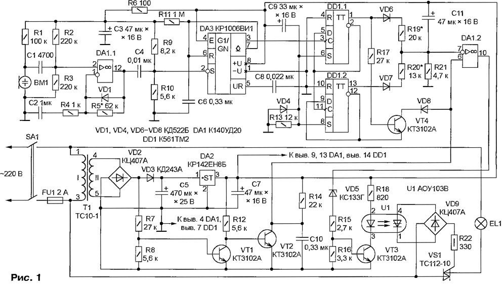
Control circuit represented in Fig. 1. The signal passed by the microphone WM, is supplied to the amplifier - Oh DA1.1. A voltage divider R2R3 sets the operating point Oh. Through a resistor R1 to the electret microphone is supplied voltage. The capacitor C1 is separation. The gain of the negative half waves signal per unit greater than the ratio of resistance values of the resistors R5 to R4. Positive "cuts" diode VD1.

(click to enlarge)
With sufficient amplitude (more than 0.9 In) signal from the amplifier output starts the single vibrator DA3, generating a rectangular pulse with a duration of approximately 0.4-dependent time constant circuit R11C6. While the impulse not over, no noise in the microphone WM not have the effect that prevents unpredictable changes in the status of the regulator.
Resistors R9 and R10 not only set the initial voltage at pin 2 one vibrator DA3, but together with the capacitor C4 form a filter. It passes only high-frequency components, which are rich spectrum of cotton in his hands, and suppresses the low-frequency characteristic of other signals and noise.
Two trigger circuits DD1 form a counter for counting the number of claps (pulses of the single vibrator DA3). Resistors R19-R21 and the diode VD6, VD7 - ADC, the voltage output (inverting input of op-amp DA1.2) depends on status of triggers, i.e. the number of claps. Capacitor C11 provides the relatively slow transition from one voltage level to another.
At power-up the positive momentum generated by the circuit R13C9VD4, sets the counter to its original state with a high logic level on the pins 1 and 13. The voltage on the inverting input of op-amp DA1.2 maximum, as resistors R19 and R20 connected essentially in parallel through the open diodes VD6 and VD7. In this open state, the transistor VT4, the emitter - a logic low with inverted output trigger DD1.2 (pin 12), and through resistor R17 to the base circuit current flows. The purpose of this transistor will be discussed below.
After the first cotton both of the flip-flop will change its state and the voltage on inverting input of op-amp DA1.2 will be zero because the diode VD6 and VD7 will be closed Second cotton will establish a high level at the output of the trigger DD1.1, leaving the state of the trigger DD1.2 unchanged. Now the diode VD6 open, VD7 closed and the output voltage of the ADC generates a resistive divider R19R21. Third cotton will change the state of both triggers. Diode VD6 is closed, a VD7 open. The output voltage will set the divider R20R21. And finally, the fourth cotton will return the device to its original state. Further claps will lead to the repetition of the same cycle.
Timing diagrams of signals at characteristic points depicted on dimmer Fig. 2 To the base of transistor VT1 filed unflattened pulsating voltage with the anode of the diode VD3 (the output of the rectifier diode on the bridge VD2). At the end of each halftime and at the beginning of next this transistor is temporarily closed, a VT2 - open and discharges the capacitor C10. After closing the transistor VT2 the capacitor is charged through the resistor R14 and the voltage at the noninverting input (pin 6) Oh DA1.2 grows almost linearly.

(click to enlarge)
OH DA1.2 (employee in this case, comparator) generates at the output (pin 10) a sequence of positive pulses of a duration that is greater than the less than the voltage at inverting input (pin 7) of op amp. If it is zero, the output of op-amp positive DC voltage, and if it exceeds the amplitude sawtooth at pin 6, the output voltage of the shelter is close to zero, but not equal to him because of the characteristics of the device OS To low level output voltage Oh DA1.2, the transistor VT3 was securely closed, there is provided a Zener diode VD5, "cut-off" the excess voltage.
At some combination of the values of resistors R19-R21, the voltage at inverting the input of op-amp DA1.2 in the initial state of the controller may be lower amplitude "saw", lamp EL1 is turned off completely. For exceptions this situation provided the transistor VT4, of above. When he opened, the sawtooth voltage is limited at a very low level. Diode VD8 eliminates the effect of the transistor VT4 on the operation of the generator when the output 13 trigger DD1.2 are set to high logic level.
In the collector circuit of transistor VT3 is included emitting diode of the optocoupler U1. If the transistor is open, open and photodirector optocoupler, trailing through the diode bridge VD9 and resistor R22 chain offices triac VS1. Depending on the share the duration of each half cycle during which the triac is open, change the effective value of the incoming lamp EL1 voltage and the brightness of its glow. Since the triac is opened and the positive and negative half-cycles, twinkling lights discreetly and at reduced brightness.
Establishing dimmer begin with installation of the necessary acoustic sensitivity. Note that with the increase in the value of the resistor R5 is growing not only the sensitivity, but also the risk of false positives from extraneous sounds. The levels of intermediate brightness levels can be changed at their discretion, selecting the values of resistors R19 and R20. Increase the capacity of the capacitor C11 results in slower growth or decline in brightness after another cotton.
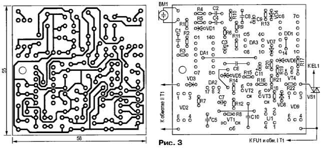
The printed circuit Board dimmer and the items on it are depicted on Fig. 3. Capacitors C6 and C10 should be a film series K73-9 or K73-17. Ceramic capacitors (K10-17 or imported) unwanted here because large TKE. However, you can apply them as C1, C2, C4 and C8. Oxide capacitors - any suitable dimensions and operating voltage. Power resistors R18 and R22 should not be less than indicated in the diagram.

Zener XG can be replaced by another (for example, imported) with the same or a little less stress and possibly less minimum current stabilization. In the VD3 diode rectifier will fit any with a valid direct current less than 0.3 A, instead of the other diodes series CD, KD521, KD522. Transistors VT1-VT4 - any structure n-p-n with a valid collector current of at least 100 mA and ratio h21e over 50. Chip CUT can be replaced by CRUD, KTM - KTM, and instead of the integral stabilizer CREB to apply KREN (with any letter index), KREN or imported with the voltage stabilization 12 V, permissible current load of at least 50 mA.
Electret microphone WM can be replaced electrodynamic, in this case the resistor R1 should not be installed. Triac TS-10 can be replaced by COW or COG. With a total power of lamps lamp 100 watts triac must be installed on a heat sink. Fuse-link FU1 select trip current, exceeding 1.5...2 times the rated current of the lamp.
The transformer T1 is any that provides the voltage at the secondary winding 12... 16 V at a current of not less than 50 mA. When you have a choice, preference should be given the transformer with the minimum no-load current value of the primary winding.
Described acoustic dimmer not difficult to turn into the touch. It is enough to replace the microphone WM and resistor R1 metal plate connected to the left (the scheme) of the output capacitor C1. The regulator will be triggered when the touch plate by hand.
Author: S. Belyaev, Tambov


