


")

This circuit operates two LED strips in pulsing mode, i.e. one LED strip goes from off state, lights up gradually, then dims gradually, etc. while the other LED strip does the contrary. Each strip can be made up from 2 to 5 LEDs at 9V supply. The two Op-Amps contained into IC1 form a triangular wave generator. The rising and falling voltage obtained at pin #7 of IC1 drives two complementary circuits formed by a 10mA constant current source (Q1, Q2 and Q5, Q6) and driver transistor (Q3 and Q6). R4, R5 & C1 are the timing components: the total period can be varied changing their values. R7 & R8 vary the LEDs brightness.
Circuit diagram: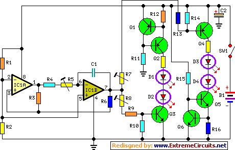 Parts:
- R1,R2_______________4K7 1/4W Resistors
- R3_________________22K 1/4W Resistor
- R4__________________1M 1/4W Resistor (See Notes)
- R5__________________2M2 1/4W Carbon Trimmer (See Notes)
- R6,R10,R11,R14,R15_10K 1/4W Resistors
- R7,R8______________47K 1/4W Carbon Trimmers (See Notes)
- R9,R13_____________27K 1/4W Resistors
- R12,R16____________56R 1/4W Resistors
- C1__________________1µF 63V Polyester Capacitor
- C2________________100µF 25V Electrolytic Capacitor
- D1-D4 etc._________5 or 3mm. LEDs (any type and color) (See Notes)
- IC1_______________LM358 Low Power Dual Op-amp
- Q1,Q2,Q4__________BC327 45V 800mA PNP Transistors
- Q3,Q5,Q6__________BC337 45V 800mA NPN Transistors
- SW1________________SPST miniature Slider Switch
- B1___________________9V PP3 Battery / Clip for PP3 Battery
- For those whishing to avoid the use of trimmers, suggested values for 9V supply are: R4=3M9, R9 & R13=47K and trimmers replaced by a short.
- Whishing to use a wall-plug adapter instead of a 9V battery, you can supply the circuit at 12V, allowing the use of up to 6 LEDs per strip, or at 15V, allowing the use of up to 7 LEDs per strip.
- In this case, the value of the trimmers R7 & R8 should be changed to 100K.