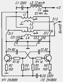
Diagram of a simple signal generator, covering the frequency range 1...30 MHz, shown in the figure. It was designed DH1NAU and DB1NV to configure SW antennas together with conventional resistive measuring bridge. The output voltage the generator is sufficient for normal operation of the bridge, if it is used germanium diode, and the led has a current full deflection of not more than 50 μa.

The generator is assembled push-pull circuit with capacitive feedback. Working frequency band is divided into two sub-bands: from 1 to 9 MHz and 9 MHz to 30 MHz. Ranges select switch S1 has two positions and three directions. Great the overlap in frequency at each sub-band involves the use with a variable capacitor with Vernier a big slowdown. Otherwise it will be difficult installation of the operating frequency.
In this design you can use high-frequency transistors series CT, CT and the like. Variable capacitor from radio receiver. Coils are wound on frames with a diameter of 8 mm with podstroechnik from carbonyl iron. Coil L1 (sub-band 1...9 MHz) has 60 turns wire diameter of 0.8 mm. the Withdrawal made from the middle. The coil L2 has six turns of the same wire. It is wound over about halfway L1 (wherever a diversion). Coils L3 and L4 are respectively 12 turns (with a branch of the middle) and two turns.
Nourish the signal generator from a source of voltage 6...9 V.
The original article (G. Grunbeck, J. Jirmann. Wireless antennas adjustment - und autonom netzunabhanig. - Funkamateur, 1998, No. 1, S. 102-106) contains a description of two signal generators - on strips 138 and 150 and 400...450 MHz, and a description actually measuring bridge. Because this bridge is used on УSW, he performed on parts that are intended for surface mounting.
Authors: G. Grunbeck, J. Jirmann


