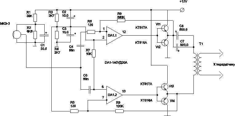
This modulator I developed for portable radio, but its good characteristics allow to use it in powerful enough stationary transmitters AM. When you change the voltage, please note the mode of operation microphone DC, or use the microphone of another type, such as "Pine".
Chip CUA unfortunately, you have to lower values of the supply voltage, at least for me this quality the work did not suit. On the other hand, increasing the voltage increases the power dissipated at the output transistors, so it is better to replace them with more powerful type CT, CT. The lack of initial bias on the terminal transistors does not have a strong impact on the quality of the speech signal, since the output transformer is sufficient to effectively suppress higher harmonics.

Fig.1
Transformer to perform better on iron core cross section of at least 200 square millimeters, the primary winding has at least 500 turns wire PEL 0.3. Secondary dangle a thicker wire, number of coils is calculated using coefficient of 0.65(efficiency of the transformer), to obtain the necessary voltage amplitude modulation. The primary the coil in my modulator was obtained up to 20 volts peak-to-peak at 20 mV signal from the microphone... You can apply a ferrite core, but have to push high frequencies, aligning the through AFC in need the frequency band.
PCB was not designed, for reasons of economy of space. My humble experience has shown that sometimes volume curve the installation takes up less space than the most sophisticated printed circuit Board. In this case, the chip, and electrolytes transistors were glued to the transformer in convenient locations, and everything else on them "waves". The exception was only the microphone. Preferably the entire modulator to saarnisaari (just in case).
Author: Dmitry Malakhov; Publication: N. Bolshakov, rf.atnn.ru


