Recently radio-athletes are Amateurs, and ultracataclasite "Fox hunters" is increasingly used in the apparatus of an integrated circuit. Now on chips, you can perform almost the entire reception and a large part of the transmission path of the transceiver, to produce for radio "Fox hunt". The use of chips not only significantly simplifies the design of sports equipment, reduces its size and weight. There is a real opportunity to create a high-quality equipment, manufacture of discrete items, was essentially inaccessible to a wide range of radio fans. Digital scale, high quality phase-locked loop frequency, display devices (displays) - this is not a complete list of units, the introduction of which in sports equipment has only been possible through the use of integrated circuits.
In sports LW and УSW equipment are increasingly used in digital circuits. Of them in Amateur practice most widespread chip series C and 155, which have sufficiently high performance, good load-carrying capacity, easily aligned with the nodes, transistors. These chips perform an automatic Telegraph keys, gauges, Morse code, digital scale, individual components of sports equipment, etc.
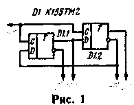
Using D-flip-flops, it is easy, for example, to build a phase shifter with a phase shift of 0°-180°-90°-270° (Fig. 1). Compared to described in "Radio", 1977, No. 6, it provides higher accuracy of phase relations, as there is no pre-trigger fission that adds additional uncertainty.

In Fig. 2 is a diagram of the mixer on a D-trigger, is different from analog not only its simplicity, but also because at its output forms no "products" conversion, except the difference frequency and its harmonics. This allows you to .some cases to abandon the filtering system. Signals with frequencies f1 and f2 is fed to the inputs D and C. the signals at the inputs does not matter: in any case, the trigger outputs will appear the signal of the difference frequency. It is important to, first, the input had a fairly steep front, and secondly that the frequencies f1 and f2 differ from each other by not more than 30...35%. The shape of the signal at the input D is not particularly critical.
On the basis of such a mixer is possible to build effective threshold detector for the receiver "lisanova".
The Telegraph signal lo is fed to the input, and the if signal is input D. Until the positive half wave voltage of the inverter reaches level 2...2.4 V, the signal at the detector output will be absent. Such a detector has a pronounced threshold limits and is very effective in the middle search. If the intermediate frequency in the receiver "lisanova" less than 1 MHz, it is wise to use economical triggers a series of K134.
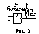
Logic elements can also be used to build analog mixers, which can be obtained as the difference and sum frequency of the two oscillations. One of the options on the mixer element "2I-NOT" shown in Fig. 3. In principle, it is no different from the usual, performed on the analog elements. The frequency ratio here can be any, and the signal difference or sum frequency spectrum of the output signal is marked with the corresponding filter.
Digital and analog mixers described above are unsuitable for the construction of SSB detectors, modulators and converters. However, using digital circuits, you can create and linear mixers.
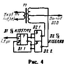
One variant of this mixer (it was proposed by Polyakov, RA3AAE) shown in Fig. 4. It is a balanced modulator on the basis of key Converter and can be used to build shapers or converters single-sideband signal. The modulator does not need to establish. When you use a matching transformer (T1) from the transistor radio carrier frequency is suppressed at least 40 dB. To suppress more should be thoroughly symmetrical secondary winding of the transformer. Strictly speaking, in this modulator, the carrier signal is not" must be present at the output, as it is not supplied to the transformer, but only determines the switching frequency of the electronic keys made on the elements of D2.1 and D2.2, which connect the terminals of the secondary windings with a common wire.
However, in a real device due to lack of symmetry of the secondary winding of the transformer at the output always has a voltage of carrier frequency.
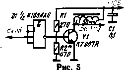
Digital circuits can be used to excite low-power output stages Telegraph transmitters, such as transmitters for "hunting for foxes" (Fig. 5). This output stage operates in a mode close to class B. In essence, the transistor V1 is excited by a rectangular pulse, G. close in shape to the square wave, the output of the transmitter must be applied quite effective filtering of harmonics.
At a frequency of 3.5 MHz input power can be 10...12 watts. Resistor R2 is selected so that it does not exceed the maximum allowable for the transistor V1 values.
In Amateur shortwave equipment often use the method of multiplying the frequency of the low frequency oscillator to obtain a frequency higher frequency ranges. The device is an overly-critical setting. In addition, with the increase of the number of harmonics decreases the signal amplitude. Much easier this task can be solved by dividing the frequency of the master oscillator, using elements of digital technology (Fig. 6). On the triggers D1, D2.1 is assembled, the frequency divider, on-chip D3 - electronic keys. Depending on the specific conditions of the master oscillator may be smooth, kartsovnik, interpolation or covered by the PLL.
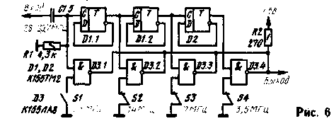
It should be borne in mind that the frequencies corresponding to the ten meter Amateur band, exceed the maximum switching frequency guaranteed for triggers K155 series. So not every chip K155TM2 will work in the first divider stage. Similarly, not every chip K155LA8 will effectively skip over these frequencies. Therefore, by repeating this device may require the selection of D1 and D3. As an example, transmitting device, which uses digital circuits, can cause the transmitter to "Fox hunt" developed by R. Guevin (UA6XBP) and A. Volchenko. He exhibited at the 28th all-Union exhibition of Amateur radio operators, designers DOSAAF. Diagram of the transmitter shown in Fig. 7. Its output power in the range of 3.5 MHz is about 2 W, in the range of 28 MHz to about 1.5 watts.
In the range of 28 MHz driving signal generator configured transistor VI, through the elements of D1.1 and D1.2 is supplied to the power amplifier transistor V2 and then to the antenna. Switch S1, if necessary, include a tone generator (elements of D1.3. D1.4, D2.1), the signal frequency of about 1000 Hz which is supplied to the second input element D1.1, performs in this case the role of the amplitude modulator.
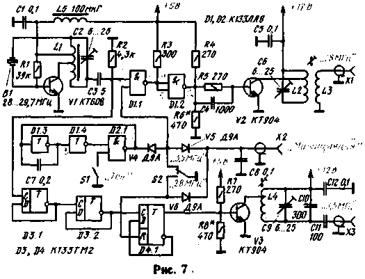
When working in the range of 3.5 MHz signal flow through the element D1.1 blocked logic 0 is supplied through the contacts of switch S2 on the bottom (the scheme) the input of this element. The signal of the master oscillator is divided by D3 triggers.1, D3.2, D4.1 to 8 and from the output of the last flip-flop is supplied to the power amplifier is performed on the transistor V3. Manipulation can be performed using a Telegraph key, and an automatic manipulator.
Coil L1 in the transmitter is made on the annular ferrite core MVC (size CH HH.5). It contains 13 turns of wire PELSHO 0,35 (elbows between 3 and 6 turns, counting from the scheme). Coil L2 to L4 is wound on the frame with a diameter of 10 mm. Coil L2 must contain 15 turns of PEV-1 to 0.8, L3 (L2 wound on top) - 6 turns PELSHO 0,35, L4 - 40 turns PELSHO of 0.15. The coils L2 and L4 bends should be done in about one-third of the turns (counting from the scheme). The trimmers have coils L2-L4 - SCR-1.
Author: T. krymshamhalov (UA6XAC), Nalchik; Publication: N. Bolshakov, rf.atnn.ru


