


")

The article describes a simple regulated switching power supply (SMPS), which can be placed in body size of a matchbox. Device has high specific capacity, good reproducibility, and is not afraid overcurrent.
Main technical characteristics:
- supply voltage AC, .....220±20%;
- power supply voltage frequency, Hz.....40…400;
- power consumption with no load, W, not more.....0,31;
- conversion frequency, kHz.....115 140…;
- nominal output voltage, V.....9;
- maximum output power W.....10;
- maximum efficiency, %.....88;
- the power density W/dm3.....300;
- weight (without housing), g, not more.....28.
Description miniature SMPS have been repeatedly published in the pages magazine "Radio". Typically, this device with a small output power. One of these SMPS [1] gave a load capacity of up to 0,63 W being the one of the most powerful sources among those that fit in a matchbox or in dimensions Krona battery [2]. In addition, these sources had low efficiency, usually no more than 35%.
The proposed flyback SMPS can also to put it in a matchbox, but its output power 15 times, and the efficiency 2.5 times more than the analogue [1]. To achieve such a high energy performance managed through the use of specialized chip TNY255P family TinySwitch Power integrations company [3, p. 479, 480] ARIA stabilizes output the voltage has protection against overload and short circuit in the load by skipping pulses, and used chip contains nodes of protection from overheating. More detailed information on the parameters and characteristics of this chip TNY255P can be obtained on the website.
The SMPS circuit shown in Fig. 1.
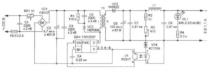
Fig. 1
Fuse FU1 protects against accidental situations. The thermistor RK1 limits the pulse charging current of the capacitor C2 to secure for the diode bridge values VD1, and together with the capacitor C1 it forms an RC filter, used to reduce impulse noise penetrating from SMPS in a network. VD1 diode bridge rectifies the mains voltage, the capacitor C2 - smoothing. The emission voltage of the primary winding transformer T1 reduces the damping circuit R1C5VD2. The capacitor C4 is the power supply filter, which is supplied with the internal elements of the circuits DA1, nominal capacity may be in the range of 0,1…the 4.7 UF.
The output rectifier is assembled on the Schottky diode VD3, output voltage ripple smooths LC filter C6C7L1C8. Elements R2, R3, and VD4 U1 jointly provide with chip DA1 stabilization of the output voltage when the load current and the mains voltage. Circuit activation is performed on the led HL1 and the current limiting resistor R4.
Applied fixed resistors MLT, C2-23, P1-4, trimmer - N-1 firm Bourns or domestic analogue SDR-19a, oxide capacitors - import, C1, C3 and C5 - high voltage ceramic CD2200Z5V, DEBB33D222KA2B, C4, C7, C8 - K10-506. The series thermistor NTC (negative. TKS) - SCK-103. Chip TNY255P interchangeable on TNY255G, TNY256P or TNY256G. diode HER208 - HER106, HER107, HER206, HER207, 1N4937, FR306 or BY399, diode 1N5822 - SR360, 31DQ04, 31DQ06, 90SQ045. Zener COP 170 ╟ can be replaced by a Zener XA, XA, and the optocoupler RS - LTV817, RS, LTV816. Led - any miniature, preferably blue or green glow. Fuse FU1 - constructive, it is formed on a printed circuit Board conductor, it is possible to replace cut copper wires, such as sew-2, with a diameter of 0.03 mm.
For the manufacture of the transformer applied magnetic armour. B18 (without the podstroechnik) of ferrite 2000NM. The primary winding has 182 round wire diameter of 0.11 mm, and the secondary consists of 20 turns of wire with a diameter of 0.6 mm Between the windings it is necessary to lay two layers of Mylar or leacockanimal tape, to impregnate them with paraffin to reduce acoustic noise. between the cups the magnetic circuit is necessary to make a gap of 0.16…0.23 mm, which can be use a gasket made of PTFE, fiberglass or cardboard. The inductor is wound on the magnetic core size CHH of ferrite and 2000NM contains 16 turns of wire with a diameter of 0.6 mm at an output current of up to 200…300 mA and 3-4 turns of wire with a diameter of 0.8 mm at a current of 1.1 A. Sharp edges of the magnetic core must be dulled with sandpaper and wrap a layer leacockanimal tape. For winding of the transformer and inductor should to apply the wire marks sew-2, PATM, PETV-1, petv-2, PAT-200-1.
Drawing of the PCB shown in Fig. 2, it is made of one-sided foiled fiberglass thickness 1…1.5 mm. Chip set in panel, cups of the magnetic core is compressed between a and fastened to the Board two brass screws, spun from opposite sides in a brass bushing. All the resistors and diodes are mounted perpendicular to the Board.
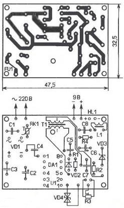
Fig. 2
Appearance fees collected by the it is shown in Fig. 3. After checking and establishing its place in the body of the insulating material. The establishment of the SMPS is reduced to accurate setting of the output voltage trimming resistor R3.
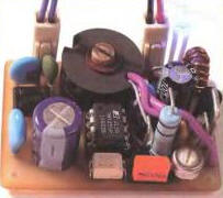
Fig. 3
Literature
1. Moscato E. Pulse SP in a matchbox. Radio, 2005, № 6, p. 26, 27.
2. Solonin V. Network in the dimensions of "the Crown". Radio, 1999, No. 2, pp. 37, 44.
3. Circuits for switching power supplies and their application. 2nd edition, revised and expanded. - M.: Publishing house Dodeca-XXI, 2001.
4. TNV253/254/255. - <http://www.allcomponents.ru/pdf/powerint/tny255p.pdf>.
Author: E. Moscato, Taganrog, Rostov region