During the development and testing of a switching power supply ham radio operators often faced with a situation where it seems to be correctly assembled unit power "refuses" to work. Quite erroneously change the polarity of the at least one of several rectifier diodes on the output device or to violate the phasing of any winding of the transformer, and the consequences can be very unpredictable, until the damage is very expensive PWM controllers and switching transistors. To prevent such an undesirable phenomenon will help universal test, which will be discussed in this article.
You should pay attention to the fact that during the test the SMPS used two independent power source. One of them, low-current (Imax=0.2 A), with output voltage 10... 15 V after an additional stabilization chip DA1 at 8 nourishes In the control circuit, the display and protect your device. Second, high current (Imax=5A) is a source of test voltage for check the elements. For this purpose it is convenient to use staffing network the rectifier SMPS. Therefore, although the transformer T1 and the optocoupler U1 device provide galvanic isolation between these sources, during check to avoid electric shock, remember, that the circuit connected to the transistor VT2 and resistor R9, is under the mains voltage.
If the amplitude of the sawtooth voltage pulses across the resistor R9 will exceed a threshold value at which the current emitting diode of the optocoupler U1 will be sufficient for opening his phototransistor signal overload with collector the latter will prevent the passage of pulses from the generator. Connected in parallel the plot of the collector-emitter of the phototransistor capacitor C3 of small capacity increases the immunity of the device.
In the described test applied to the switching transistor IRFBC40, which the maximum drain current is equal to 6.2, and the voltage of the source-drain - Threshold 600 V. the selected level of current 5 A, and the voltage protection trip will be 0,33 Ohm x 5 And = 1.65 V. the Power dissipated by the current sensor (R9) fill factor pulses D - 1 shall be not less than (1,65)2/0,33 to 8.25 watts. When the device used to evaluate the load capacity of SMPS (D=0,2), floor power needs 8,25x0,2 = 1.65 W. If the test is supposed to be used just for testing inductive elements SMPS, as in our case, taking into account sawtooth shaped current pulse power resistor should not be less than 1,65x0,5=0,825 watts.
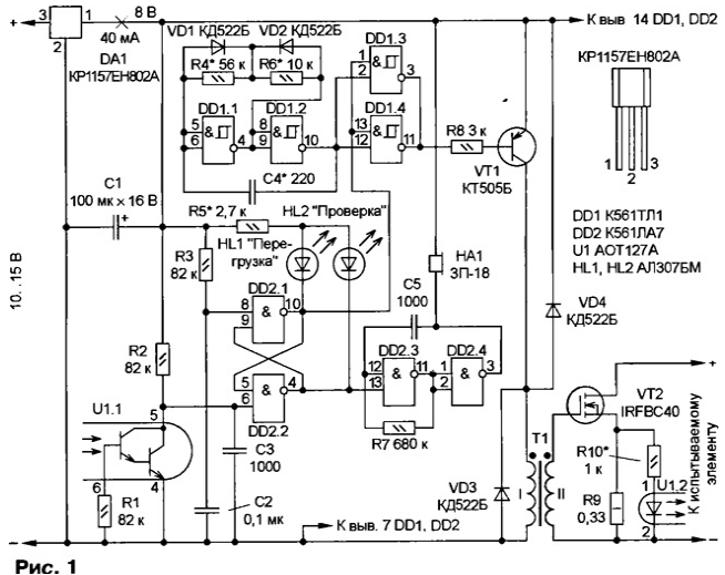
Of course, import the transistor can be replaced by domestic or CPU similar, but for them, the parameters of the current sensor will need to be converted into according to the above ratios and taken into account when establishing in the device.
Consider the work of protection circuits on the elements of DD2.1 and DD2.2.
To the upper circuit on the input of the RS flip-flop (pin 8 DD2) connected chain R3C2, the time constant of which is equal to 8.2 MS. It provides a time delay the appearance at the entrance of the high level needed to trigger node protection to bring to its original state.
This feature is illustrated in Fig. 2 the presence of a time interval between tmin turning the device on and start check the SMPS.
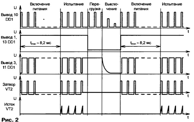
Practically, this imposes restrictions on the order of switching these two independent sources of power: you must first enable low, then high current, and to turn off in the reverse sequence, first the high and then low. Observance of this rule will prevent damage to the switching transistor VT2 by the first pulse at the time turn on the device. In addition, I recommend when you first turn on the SMPS not to apply full voltage and gradually increase it, for example, laboratory autotransformer.
In case of overload of the switching transistor RS-flip-flop switches to zero state. On pins 1, 13 elements DD1.3 and DD1.4 high level replaced low, and the further passage of pulses is blocked. Switch RS-flip-flop disables the led HL2 "Check" and includes HL1 led "Overload". The generator on the elements of DD2.3 and DD2.4 produces a warning beep. After turning off the power and removing overload after a time required to discharge the capacitors C1 and C2, the device is ready to re-enable.
The use of the device for the evaluation of the saturation current of the inductor used in the output filter SMPS, has its own characteristics. Consider them in detail.
In Fig. 3 shows the wiring diagram of the test in this case.
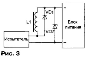
The power supply unit (PSU) - high current: the maximum current must exceed selected for the circuit protection device of a threshold value of 5 A. in Parallel test the throttle connect the diode VD1. Here it is permissible to use KDE or similar. The switching frequency can be very large, especially for inductors with inductance in hundreds and thousands of microgenre. Therefore, at the time measurement of parameters of the throttle may need greater reduction operating frequency at a constant (or adjustable) pulse duration. Performance can also be improved by the introduction of the Zener diode VD2 displacement the voltage is slightly higher than the measurement. It is also desirable that the voltage at the output of the PSU was adjustable.
In parallel with the resistor R9 tester connect the oscilloscope. Possible options And and B the observed diagrams of the voltage drop across the current sensor Ur9, and voltage U3 and the gate of the switching transistor shown in Fig. 4.
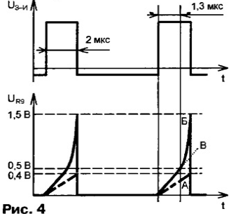
As is known, the voltage U applied to the throttle, causing a linear increase current D1 in it. This relationship is expressed mathematically by the equation AI=(U/L)Δt or, in other words, a voltage of 1 V is applied to the inductor with an inductance of 1 GN will cause 1 with an increase in the current in it is 1 A. If the numerator and denominator the fraction in the right part of equality to multiply by a factor of 10-6, we get important the result: to determine the variation of the current in D1 in amperes formula can substitute the inductance in microhenry, and the time in microseconds that we we will use the measurements.
Assume that the output of the PSU is set to the voltage U = 20 V, and at a certain the selected throttle chart voltage UR9 takes the form A (Fig. 4). Rate the properties of the inductor.
It is obvious that the peak value of the current I = U/R = 0,4/0,33 - 1.2 A, and can be done the conclusion that evaluated the throttle will be fully operational when the filtering of current up to 1.2 A. moreover, by using a test can be evaluated the inductance of the inductor, which is necessary to use the relation L = (U/AI)At. Substituting the appropriate values, we get L = (20/1,2)2 - 33 µh. Of course, on the accuracy of determination is influenced by many parameters: the tolerance value current sense resistor, the error voltage and time interval with an oscilloscope, current limiting effect in measuring circuit caused by the resistance of the inductor and the resistor R9, and some other factors. But according to a rough estimate, the total error measurement of inductance by this method will not exceed 20 %. Such precision quite sufficient for the evaluation of the filtering properties of the inductor in the output filter SMPS.
Now, without changing the throttle, increase the voltage at the output of the PSU to 40 and In get option B the diagram shown in Fig. 4. It is important that the peak value voltage UR9 did not exceed thresholds established for chains protection, otherwise the measurement will be impossible. As can be seen from the figure, this condition made. Calculations similar to the previous one, allow us to conclude:
- the limiting value of the current (saturation current) is 1.5 A;
- the inductance of the inductor is equal to 34.5 µh.
The slight discrepancy between the results point to increased accuracy measurements, due to the difficulty in determining the inflection point on the curve B. Usually for this purpose use is made of the stencil paper applied to izobrajeniu curve on the oscilloscope screen, as illustrated on line In Fig. 4. Therefore, during the measurement, it is advisable to reduce stress at the output of the PSU to the value at which the chart is taking a strictly linear view, such A line, and use the results to estimate the inductance throttle and the saturation current in it.
The increase in the probability of occurrence of saturation in the inductor with a small current associated with the use of closed magnetic cores made of a material with high magnetic permeability (more than 200). To avoid saturation, you should use rings magnetodielectric based alsever or molybdenum-permalloy alloys or enter non-magnetic gap. If you compare the ferrite ring, W-shaped armor and magnetic circuits, it should be recognized that more technological in the sense of a non-magnetic gap, the last two, but not impossible use as subanalysis of magnetic ferrite segments rods used in radio receivers for magnetic antennas (lower the magnetic permeability, the better).
And the last option is the use of the device during testing SMPS - as adjustable dummy load, and the load pulse, which is especially true for power supplies used in the composition of USC. Peak, maximum, average, music, heat and a variety of other terms, characterizing the power derived from impulse effects, were not in vain invented by experts for the evaluation of this class of radio devices. Of course, in this case, the generator in the test must be rebuilt on the range of sound frequencies and to provide for the adjustment of the duty cycle of the switching pulses, as recommended in the beginning of the article. The measurements should pay attention to the thermal regime circuits DA1 and the transistor VT1. Perhaps when the fill factor of the pulses close to 1, which will require replacement more powerful elements.
Depending on the output power and output voltage of the SMPS will need several resistors in units of tens of ohms power dissipation with a capacity of 30 to 50 watts. In their absence as the equivalent load acceptable use automotive lamps with an operating voltage of 12 V, and among them easy to pick up copies, are designed for a rated current of shares to tens of amps. If the maximum power dissipation when current through the switching transistor is $ 5 And will be not enough to fully load SMPS, high-voltage field-effect transistor IRFBC40 you can substitute low-voltage, for example, IRFZ48N whose maximum continuous (average) current of 45 a, And pulse - to 210 A.
Connection diagram when using the device as an adjustable equivalent impulse loads is shown in Fig. 5.
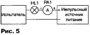
Included in the measuring circuit the ammeter will show the average value of current. If the ammeter readings divided by the fill factor of the pulses, obtain the amplitude (peak) value of the current in the load circuit. When the fill factor of the pulses close to 1, the load for SMPS max.
The switching transistor VT2 in the test should be mounted on heatsink with an area of 100...200 cm2. Integrated stabilizer replace CREA foreign counterpart 78L82 or more powerful adjustable domestic CREA, CREB. Chip CTL permissible to replace CLA. Instead CTB you can use any high frequency medium power transistor appropriate structure. Piezoceramic a sound projector HA1 - any available. Diodes CDB interchangeable with any low-power silicon, for example, series KD521, KD522, OPTRON - any of the series AT, AT. LEDs - with any visible luminescence at a current of about 5 mA. The capacitor C1 is any oxide the specified capacity, the other all-ceramic. All resistors MLT, C1-4, C2-23, except for imported R9.
The transformer T1 pulse - fit-5. If this is not found, transformer make yourself. Its magnetic circuit are the two stacked together ring K10h6h3 ferrite magnetic permeability of 1500...2000. Sharp edges rings scroogled needle files, a magnetic circuit is covered with an insulating varnish and after his drying is wound 100 turns in the two wires PELSHO of 0.12. To connect the transformer should take into account the phasing of the windings I and II, shown in Fig. 1.
The transformer can also be manufactured on the basis of shell-type magnetic circuits or B B18. In this case, the winding containing 50...70 turns of wire sew-2 0,12-0,17 must be reliably insulated from each other.
Establishing device start with checking the settings of the pulses at the output generator (pin 10 DD1). If necessary, adjust the selection capacity capacitor C4 and the resistors R4 and R6. Then disconnect the upper the schema of the output resistor R10 and connect it to the positive output adjustable the power source negative terminal of which is connected to the output 2 of the optocoupler U1. Gradually increasing the voltage, record the time of the disappearance of pulses per the outputs of the elements DD1.3, DD1.4. Choosing the resistor R10, making the lack of pulses at a voltage of 1.65±0.05 V, and then reconnect.
In the next stage of the selection of the resistor R5 sets the current of the LEDs HL1, HL2 about 5 mA. At least check the polarity of the pulses at the gate transistor VT2. If they do not correspond to Fig. 2, change the phasing of one of the windings of the transformer T1.
The final stage - monitoring performance of the switching transistor VT2, for which the device is connected to the network check the rectifier SMPS in accordance with Fig. 5. In the SMPS must be a network switch voltage, fuse 2 A and the circuit limits the inrush current. In the load using an illumination lamp for a voltage of 220 V power 60 watts. Preferably, but not necessarily in the chain to turn on the DC ammeter the measurement limit of 0.5 A. when the mains rectifier to test several times served and remove the supply voltage 10...15 V. When operating the generator lamp will glow in the half-heat, and the ammeter will show a current of about 0.08 A. taking care with an oscilloscope control pulses on the drain of the transistor VT2. If the transistor is defective, the lamp will glow half brighter and will not respond to shutdown supply voltage of the device. Faulty transistor should be replaced, and after additional testing of the device is ready for operation.
To extend the capabilities of the device can be supplemented by two switches, commuting sets of resistors R4, R6 and capacitor C4 of different sizes, through establishing several fixed values of frequency and the fill factor of the pulses.
Author: S. Kosenko, Voronezh


