


")

Describe the power supply is built from the available elements. It almost does not require networking works in a wide range input AC voltage, shielded from overcurrent.
The proposed block power allows to obtain a stabilized output voltage from 1 To almost to the value of the rectified voltage from the secondary winding of the transformer. Transistor VT1 is assembled node comparison: engine with variable resistor R3 is supplied to the base portion of the reference voltage (set source reference voltage VD5VD6HL1R1), and the emitter is the output voltage with divider R14R15. The signal the error is fed to the current amplifier, which is made on the transistor VT2, which controls the control transistor VT4.
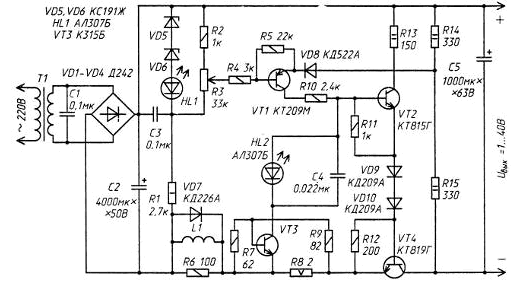
When a short circuit at the output of the power supply or excessive load current increases the voltage drop across the resistor R8.The transistor VT3 opens and bypasses the base circuit of the transistor VT2, thereby limiting the load current. Led HL2 signals the inclusion of protection against overcurrent. In the case of circuit when the current limit is not instantaneous. The inductor L1 prevents the rapid increase in current through the transistor VT4, and diode VD7 reduces the power surge of accidental disconnection of the load from the block power.
To regulate the current tripping in the open circuit between the resistors R7 and R9 must to include a variable resistor of 250 Ω and the engine is connected to the base of transistor VТ3. The current value can be adjusted from 400 mA to 1.9 A.
In the power source we apply any transformer with a voltage in the secondary winding 9 to 40 V. However, at low voltages the resistance of the resistors R1, R2, R9, R13-R15 should reduce by about two times and pick the Zener diodes VD5, VD6, so that the voltage across the resistor R1 was roughly half of the voltage on the capacitor C2.
The inductor L1 contains 120 turns of wire PEL 0,6 wound on the mandrel with a diameter of 8 mm. Transistor CTM (VT1)to replace CT with any letter index, KT (W-M), CT (W-M), CT (A, B). Instead transistor CTG (VT2) apply any series CT or other similar structures with a valid voltage collector-emitter voltage not less than the power. The transistor VT4 - CTA, CTA, CTA, series CT, CT, CT, CT or any powerful with valid the collector current of at least 5 A and allowable voltage collector-emitter more the supply voltage. Transistors VT2 and VT4 should be placed on a heat sink. Diodes VD1 - VD4 - any rectifier with a valid direct current of 5 A and reverse voltage less voltage on the secondary winding of the transformer. The LEDs can be applied any type.
Author: A. Pogorelsky