In shops, kiosks underground transitions, on the radio you can buy so-called adapters, decorated in the form of a plug. Large output voltage ripple and dependence on the load current food hamper from them any of electronic equipment. How to stabilize the output voltage of such adapters and covered in this article.
To fix the "round" values the output voltage is the easiest way to use the chip KREN and KREN with the appropriate alphabetic indices, setting them on the sink in the adapter case and complementing the output capacitor not less than 10 µf. If you need non-standard voltage, should apply a chip CREA.
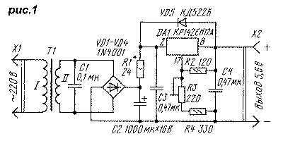
In Fig. 1 is a diagram of charge-the feeding device for portable radio has four battery NDEF-0,45. The capacitor C1 eliminates high frequency noise, may occur during the closing of the diodes of the rectifier bridge. Output the voltage of 5.6 To establish a trimming resistor R3, and the maximum current charging (about 150 mA) - selection of resistor R1 connected a discharged battery. The unit is convenient because charging batteries is fast (4...6 hours), and they cannot be recharged.
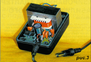
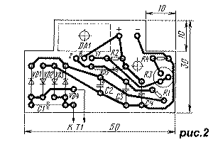
The device is assembled on the basis adapter RW-900. Drawing of the PCB shown in Fig. 2, and the appearance block in Fig. 3. Used resistors MLT: they are installed on the Board vertically, R3 - CP3-19a. Diodes VD1-VD4 and the capacitor C2 from the adapter, the rest of the RV-6. The capacitor C4 can also be set and any oxide, but its capacity should be not less than 10 μa. Diode VD5 - almost any rectifier or pulse.
DA1 chip mounted on ribbed heatsink dimensions 10x18x38 mm from industrial devices. For good cooling in the lower and upper walls of the housing adapter (orientation when turn it into a wall outlet) drilled six holes 6 mm.
If output current limiting is not required, the resistor R1 and the capacitor C3 can be eliminated. In this embodiment, the maximum the output current was 0.5 a at a voltage ripple of about 1 mV. Picking up the resistors R3 and R4, it is possible to assemble the stabilizer to any the output voltage is within the limits permitted by transformer adapter.
Using a universal adapter, it is possible to make stabilized power supply with switchable output voltage. Scheme modified adapter "FIRST ITEM NO:57" shown in Fig. 4. Secondary winding of the transformer T1 is used fully, her elbows insulated. Diodes VD5, VD6 - protective.
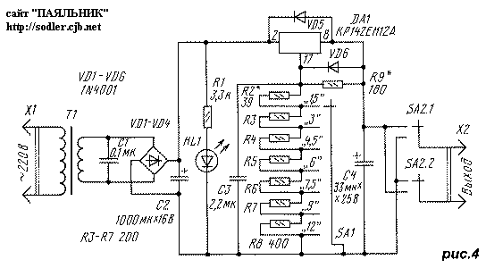
Diodes VD1-VD4, the capacitor C2, the led HL1 and the switches SA1 and SA2 from the adapter. Resistors R3-R8 are not necessarily to have a specified resistance, they can vary in any direction in 1.5 times. It is important that the resistance R3 to R7 are equal to each other with the precision 1...2%, and the resistance R8 was twice as great because they determined the error of the output voltage.
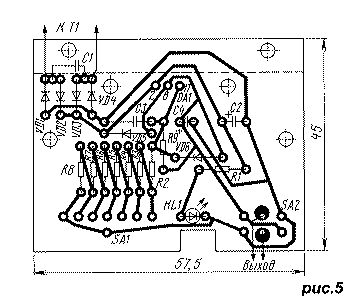
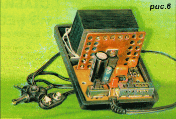
All elements, except the transformer T1, installed on a circuit Board, a drawing of which is shown in Fig. 5, and the external view of the device in Fig. 6.
For drilling mounting holes and holes for set switches and LEDs is convenient to use the circuit Board from used adapter as a stencil. To unsolder the switch from the circuit Board and it does not damage it, it is necessary, warming the multiple adjacent contacts by soldering, to twist or bend. Moving gradually to other contacts can unsolder the switch entirely.
DA1 chip mounted on a copper plate dimensions 52x38x1 mm, which serves as a heat sink. Plate has a flange for mounting on the Board, and around the perimeter of the drilled holes with a diameter of 4 mm for ventilation. For the same purpose in the upper and the lower walls of the housing drilled eight holes with a diameter of 6 mm.
Establishing device is to install output voltage without load selection of resistors R2 and R9. Resistor R9 you can immediately place mentioned in the scheme of resistance, and parallel to it and instead of R2 to solder the variable resistors 10 Ohm and 56 Ohm respectively. Resistor R9 is connected in parallel, establish the output voltage is 12 V, the resistor R2 is - 1.5 V. Since these settings interrelated, they should be repeated several times. Then install fixed resistors with matched resistors, and the resistor in parallel with R9 being served by printed conductors.
Stable adapter output provided current up to 200 mA. At a voltage of 12 V, the current is limited by the occurrence of pulsations, lower - temperature circuits DA1. Increase the surface of heat sink it is possible to significantly increase the output current at low output voltages.
Literature
Publication: www.cxem.net


