


")

The article describes a low-power power supply with a switching voltage on a specialized chip MS. In comparison with the linear pulse stabilizers have greater efficiency, less weight, compact size, but have some disadvantages, the main one being an increased level of output voltage ripple.
The proposed power unit can be used to power various appliances multifunction telephone sets, game consoles, iPod, residential calls, etc., where the use of a switching regulator will make the AC adapter is not only more economical, but also greatly facilitate its temperature. It provides an output voltage of 3.3…9 V At a current of 0.5 A. the Amplitude of the output ripple voltage does not exceed 30 mV at maximum load current. Switching regulator power supply is protected against overcurrent and from the appearance of the output high voltage.
This stabilizer can be used in the design of new power sources, and for the replacement of linear stabilizers in previously manufactured, for example, with the use of popular in the past transformers TCE-LM, TCEs-L tube-semiconductor TVs. In re-manufactured power supplies use pulse voltage stabilizer will allow you to apply a step-down transformer with less power and dimensions. The diagram of the power supply shown in Fig.1.
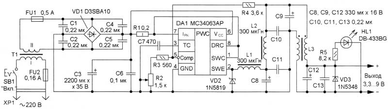
Fig. 1
The voltage across the fuse-link FU2 and a push-button switch SB1 is supplied to the primary winding of the step-down transformer T1. Remove from its secondary winding of the AC voltage via resettable fuse FU1 is fed to a bridge diode rectifier VD1. The rectified voltage ripple smoothing capacitor NW. Capacitors C1, C2, C4-C6 suppress impulse noise coming from the network, and prevents the penetration of such interference in the network from a switching regulator. He performed at a specialized integrated circuit, MSAR, which is enabled by lowering the standard scheme stable voltage Converter. This chip is operable when the input voltage up to 40 V and the maximum current of the output transistor to 1.5 A. With own current consumption sostavljaet…8 mA. The chip contains a node overload protection and short circuit in the load circuit. The resistor R1 performs the functions of the current sensor for this node. Conversion frequency set capacitor C7. The output voltage depends on the ratio of the resistances of the resistors R4 and series-connected resistors R2, R3 and may be modified within the 3.3…9 variable resistor R2. The inductor L1 is cumulative, two-section low pass filter on the inductors L2, L3 and the capacitors C8-C13 smooth output voltage ripple. HL1 led indicates its presence. The Zener diode VD3 (voltage stabilization 11 In) protects load from damaging high voltage at malfunction of the stabilizer. In excess of the output voltage 11 In the current through the Zener diode increases rapidly and resetable fuse FU1 abruptly enters a high resistance and limits the current.
All parts except the transformer T1, the holder fuse FU2 and switch SB1 placed on the PCB of one-sided foil fiberglass, a drawing of which is shown in Fig.2.
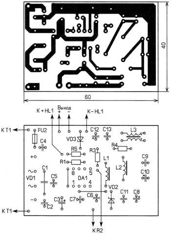
Fig. 2
If you upgrade a ready supply, it may suit already used network step-down transformer, it is necessary only to permit the voltage on the secondary winding 12…20 V and output power 8…10 watts.
Fixed resistors - C1-14, C2-23, S1-4, MLT, mon, AC - SDR-9, suitable JS4-1, SR-1A. To apply variable resistors series SP-1 is undesirable because of low reliability. Oxide capacitors - C50-35 or imported counterparts, and the rest - ceramic K10-17, km-5. Resetable fuse FU1 - MF-R050, LP60-050. Diode bridge D3SBA10 can be substituted for any of CC, DB101 - DB107, RB151-RB157 or four diodes, for example, part no 1n4001-1N4007. Diode 1N5819 replace diodes 1N5817, 1N5818, four such diodes can be replaced with a diode bridge, wherein the efficiency of the power supply will increase. Instead of the Zener diode 1N5348 suitable protective diodes 1,CE, 1,CE. The led can be any color and light (non-flashing) series CIPD, CIPD, L-53.
All chokes are wound wire sew-0,56 2, L1, L2 contain 40 turns of wire, the magnetic core size K17,5x8,2x5 mm ferrite 2000NM. Before winding the magnetic varnished cloth or wrapped in three layers of duct tape (duct tape). The inductor L3 has 6 turns of the double-folded wire wound around a magnetic core with a diameter of 10 mm and a length of 11 mm ferrite NN or with permeability of 400 (from magnetic antenna of a portable radio). If DA1 chip will be much to warm up, is to facilitate it in heat mode and, therefore, increase the reliability of the device in General, it is desirable to glue a small heatsink out of copper or brass plate dimensions 60x4,5x0,5 mm bend Her the letter "P" and paste to the bottom of the housing of the chip glue Alsil-5 or "radial". The bonding surfaces of pre-prepared in accordance with the instructions for use of glue.
When the input voltage of the Converter 12, the output voltage of 5V and output current 0.5 A consumed from the rectifier current does not exceed the 0,27 A. This confirms that the efficiency of the switching regulator can be higher than on the chip CREA. If you need a power supply with fixed output voltage, the variable resistor on the Board is replaced with a wire jumper, and the required resistance of the resistor R3 is found from the expression Uвых = 1,25(1+R4/R3). In this case, the Zener diode (or the protective diode) should be set with the voltage stabilization 1…2 more output voltage.
Author: A. Butov, S. CORBA Yaroslavl region; Publication: www.cxem.net