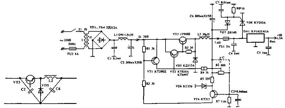
This schematic of the power source - the result of the experiment aimed at creating an easy to configure IE with high efficiency with good noise immunity.
As can be seen from the diagram presented in Fig. 1, the source consists of three parts: a Converter AC voltage 220 V 50 Hz constant 35...40 V; key pulse voltage stabilizer with Uвых=7.6 In; linear regulator with Uвых=+5 V. the basis of the scheme key regulator based on the development from the article A. Mironov ("Radio", N4/87). Schema changes are aimed at simplifying, increasing the upper limit of the input voltage. The use of diode 2D213A (VD5) is recommended A. Mironov KDA (diode with a Schottky barrier having a return branch of the current-voltage characteristics at a voltage of 25 V) provides a sharp drop in the efficiency of the Zener diode when the input voltage of 28 V and, consequently, to raise the upper limit of the input voltage from 25 V to more than 45 V.

(click to enlarge)
This modified switching regulator supports input voltages allowed for the entrance of the linear stabilizer collected on CREA, when the voltage at its input from 8.5 V to 45 V, which corresponds to a change in the mains voltage from about 44 V to 220 V.
This is enough to stabilize at short-term reduction of mains voltage (not really below 70 In) due to the inclusion of powerful consumers (low quality).
During operation of the power source, it was found that the impulse noise network only lead to premature switching of the switching transistor does not pass to the output of the stabilizer.
The use of chain VD7, VD8, R8 and FU1 eliminates possible troubles associated with the failure of the switching regulator, for example, in the breakdown of the switching transistor. To ensure the output parameters listed in Fig. 1, the transformer is wound so as to provide a rectified voltage in the range of 30...35 V At a current of 0.4 A. the Change of its output parameters in the lower side only leads to a reduction of noise immunity power source. The parameters of the inductor L1 is not critical (can't even put it in General). The capacitance of the capacitors C2 and C6 do not select less than 200 UF and 600 μf, respectively, since this leads to an increase in the ripple.
It is necessary to pay attention to the type of capacitors for these positions. The recommended type - K52, K53, or similar. It should not be used C50-16, K50-35 - this will negate the result of all Your work to ensure noise immunity.
The inductor L2 is wound on the core-type PT from alsever size CHH and contains 26 turns of wire sew-2 with a diameter of 1 mm core Sizes are not critical. However, it is still necessary to obtain the inductance is approximately equal to 30 μg. The use of ferrite magnetic core, as recommended by A. Mironov, undesirable, as it leads to deterioration of parameters of the stabilizer. When using magnetic armour choke contains 11 of turns of the eight conductors sew-1 0,35 on the core B 2000 NM.
Installation key pulse of the voltage regulator to perform better on a bilateral foil glass fiber (in this case, one side is used as a screen). The length of the wires connections on circuits C2, VT3, VD5, L2, C6, it is desirable to minimize. The most optimum arrangement of the elements presented in Fig. 2. Blocking capacitors C4, C5 are preferably placed directly on the findings DA1 CREA or near them.
The establishment of the power source is reduced to the setting of the output pulse of the key voltage regulator 7.6 8...In resistor R6 at rated load. This should oscilloscope to control the operating frequency of switching. The frequency must be within 30 to 40 kHz. If necessary, the adjustment of the frequency can be realized by selection of C3. It should be noted that depending on the capacitance C6, the resistance value of the load and input voltage operating frequency may vary within wide limits. The optimal frequency for rated load - 30...40 kHz. In the case of self-excitation switching regulator you must install an additional capacitor With a capacitance of approximately 0.01 ICF.
The value R8 is selected depending on the parameters of the Zener diode VD7.
The input voltage of the power source is easily changed by replacing VD6 on D (9V) and DA1 - KREN. You will get the output 12 V at currents up to 1.5 A.
To produce multiple voltages, it is desirable to wind the transformer T1 a separate winding for each voltage to untie the switching regulator. When the current through the switching transistor more than 1.5 A VT1 and VD5 must be installed on a small radiators.
Long-term operation of multiple power supplies, manufactured according to the described scheme, has demonstrated high reliability and noise immunity.
Author: P. Fungus, Belarus, Borisov; Publication: N. Bolshakov, rf.atnn.ru


