Compact external power supply, made in the form of the plug (also called adapters), completed with various household radios (phones, calculators, radios, etc.). Unfortunately, there are cases when this unit is designed for a mains voltage of 120 V. how you can connect to the network 220, and is discussed in the article.
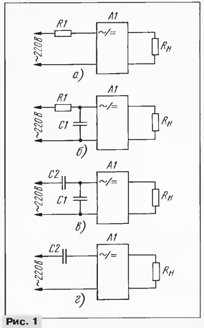
Compact remote power supply unit (A1 in Fig. 1) for input voltage 120 V, can be connected to the network 220 In at least four ways. Consider their example with Panasonic KX-A09, which equipped with cordless phones KX-TS-V. On his body indicated: input voltage - 120 V At 60 Hz; power from the network power - 6 W; output parameters: voltage - 12V; DC current of 200 mA.

At the frequency of 50 Hz, the input voltage must be reduced. Therefore, from the block power impossible to get a passport the value of the output voltage; rather only, it cannot be used to power the device, the package which he included. If the specified mains frequency 50...60 Hz, it is, of course, can be to apply for appointment.
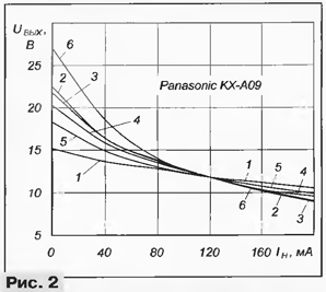
In Fig. 2 shows the dependence of the output voltage of the considered small outboard power supply from the load current when the input voltage is 105 (curve 1). To obtain comparable results, all additional elements (R1, C1, C2 in Fig. 1) are further selected so as to provide the output voltage of 11.8 V at a current of 120 mA (load resistance - 98 Ohm).
The easiest, but having the lowest efficiency, example of connection is shown in Fig. 1,and. The resistance of the resistor R1 can be calculated, as recommended in [1], and you can pick up.
The first step is to evaluate the resistance of the semi-empirical formula, ensuring the absence of overload block: R1 = 22/R where R1 is the resistance of the resistor, in kiloomah, P is the power consumed by the unit in watts. In consider the case R1 = = 22/6 = 3.6 kω. Next, connect the load and, gradually reducing the resistance of the resistor to get the required output voltage. Better, of course, use a wire variable resistor on the corresponding power. To obtain the necessary output voltage it took resistor 2,44 ohms. The dependence of the output voltage from the load current for the selected resistor R1 is represented in Fig. 2 (curve 2). It is seen that the voltage decreases with increasing current more sharply.

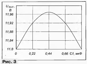
In order to reduce losses, according to the recommendation in [1] in parallel with the primary winding transformer power supply was connected to a capacitor whose capacitance is selected to provide resonance (see Fig. 1,b). In Fig. 3 shows the dependence of the output voltage from the capacitance of the capacitor. Resonance though noticeable, but its role is negligible - the voltage increases by only 1.5%. For save the output voltage at a predetermined level when the capacitance of the capacitor C1 = 0,44 IFF the resistance of the resistor R1 was increased to 2.57 ohms. Load the characteristic of the block (Fig. 2, curve 3) in this embodiment, the inclusion of the little differed from the curve 2.

It is natural to replace the resistor R1 to the capacitor (see [2], where the work capacitor divider considered for the nonlinear active load). When you save C1 = 0,44 µf capacitance of the capacitor C2 needed equal to 0.54 UF (see Fig. 1,in). Load characteristic for this case less steep (curve 4 in Fig. 2).
To an even greater extent to reduce the dependence of the output voltage from DC, increasing the capacitance of the capacitors C1 and C2. For example, when randomly selected capacity C1 = 1 µf selected to provide a predetermined voltage capacity capacitor C2 was 0.67 UF (curve 5 in Fig. 2).
On the other hand, if the stability of the output voltage when the current of each load or the load current does not change, can to exclude the capacitor C1 (see Fig. 1,g). A selection of containers you can start with the value calculated by the semiempirical formula: C2 = P/12, where C2 is the capacitance of capacitor, in the microfarad; P - unit's power, in watts. The formula takes into account margin, excluding a power supply overload. For the case the initial capacity of the capacitor C2 = 6/12 = 0.5 UF. When selected capacitance C2 = 0,76 UF and the load current from 0 to 200 mA output voltage varies from 27 to 8.9 In (curve 6, Fig. 2).
It is interesting to note that the capacitance of the capacitor C2 has turned more than for the variant in Fig. 1 ,V. This is due to the partial mutual compensation reactive currents through the capacitor C1 and the inductance of the primary winding of the transformer.
Thus, if the necessary stability of the output voltage when the the load current, the most appropriate use of the capacitor divider. If stability does not play a role, use the variant with a single condenser C2 (see Fig. 1,g).
Connectivity options of the power unit (see Fig. 1 ,a and b) impractical to apply because of the large loss of power and intense heat of the ballast resistor.
Is shown in Fig. 2 graphs show the dependence of the average value the output voltage. Really it is laid voltage ripple, its shape close to the sawtooth, and the amplitude is almost constant depending on the connection method (see Fig. 8 in [3]).
For options Fig. 1,b and g in parallel to the capacitor C2 to discharge after disconnect the power supply from the mains should be installed by a resistor several hundred of the shortfall. In addition, in the embodiment of Fig. 1,preferably in series with the capacitor C2 to connect the current limiting (at the time inclusion in the network) by a resistor 22...47 Ohms. Nominal voltage capacitors should be at least 250 In, very comfortable K73-16 and K73-17.
In all experiments, it should be remembered that the nominal voltage of the oxide the filter capacitors installed in a small external power supplies, usually 16, and therefore, the supply to them a greater voltage on any for a long period of time is undesirable.
Literature
Author: S. Biryukov, Moscow


