Powerful power source can be collected on the basis of modern integrated microchips. Integrated the chip obtained LM78H12K the source voltage of 12 V with a maximum current of 5 A. the Chip is protected against short circuit, over temperature and short-time withstand current up to 7 A. This source can be used, for example, for food or other USC devices.
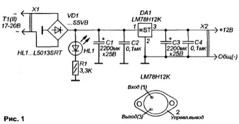
Scheme source it is shown in Fig.1.

The AC voltage from the secondary winding of the transformer T1 is supplied to a powerful diode bridge VD1, calculated the rectified current is not less than 5 A. After the diode bridge rectified voltage is supplied to the capacitors C1 and C2 performing low-frequency and high frequency filtering of the voltage, and the input chip-stabilizer DA1.
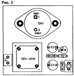
Chip made in a metal case TO-204 (to-3) with two terminals (input and output). The housing of the chip serves as a control output, and connects to the scheme using the screws and transitional contact pads on the circuit Board. On this the chip can be collected linear voltage regulator operating in low mode dropout with an output voltage of 2.3 V At currents up to 5 A. output circuits DA1 stable the voltage applied to the capacitors C3, C4 and the output of a source power. The led indicator on the HL1 performs service functions, i.e. shows the flow of voltage to the circuit Board the stabilizer.
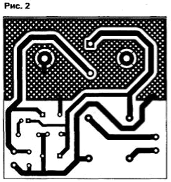
Printed circuit Board source (Fig.2) made of one-sided foil fiberglass thickness 1.5...2 mm and a size 60x60 mm.

Location electronic components on the circuit Board depicted in Fig.3.

After Board fabrication conducting path, especially power, it is necessary well be tinned with solder. On the PCB has space for installation of the radiator with the operation of the chip under test.

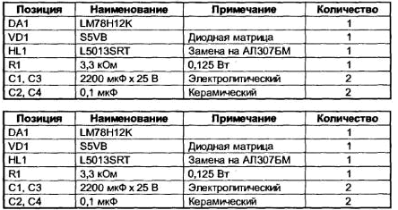
The types of details given in the table. Transformer for the source is selected in accordance with the load and is recommended, with the voltage of the secondary winding 17...20 V. In the circuit of the primary winding of the transformer you must install a fuse with a rated current 0,5...1 And the Secondary winding of the transformer is connected to the circuit Board thick stranded wire with good insulation, and as the power cord is best suited computer power cord with Euro plug.
At high loads, a diode matrix and chip-stabilizer mounted on the radiators of appropriate dimensions. For these purposes, DA1 chip specially is separately from the other components, this allows you to install the radiator with the required dispersion area. After installation and test operation of the source printed circuit Board it is advisable to varnish.
Author: A. Lickin, Ryazan


