


")

AC adapter for various makeshift structures and checking their on models you can do yourself. It's easy, and at the same time extremely useful for improving their skills, knowledge and experience, what, in fact, directed all Amateur radio activity.
Hams often requires two power supplies: one low-power, the voltage from 3 to 12 V and the load current in tens, maybe hundreds of milliamps; another powerful, for a voltage of 13.8 V with a maximum current of 5…10 A. the First need for testing various devices on layouts and in other cases where current consumption is small and "drive" for a long time just a powerful source does not make sense. The second essential for high power amplifiers, CB equipment, Amateur radios, stereos, etc., He may serve charging car batteries, if there is a node limit the maximum current. Voltage 13.8 V, which have become standard, as time and corresponds to the voltage in the vehicle electrical system when working the generator and charging the battery.
In any overage tube or tube-semiconductor TV you will find transformers, and other items for low-power, and powerful the power supply unit. Low-power unit 12 In, for example, be collected by the use ready output transformer frame scanning (TCEs) and a tube TV. In some cases suitable output transformer for tube amplifier audio frequency (TVZ), but the effective (RMS) voltage across its secondary the coil will be about 6 In, when rectified will not exceed 9 V.
How to assemble the power supply, repeatedly told in Amateur radio literature, and be repeated here. Focus only on some few known, but important points. They relate to any makeshift device.
First of all you should determine the suitability of the transformer for the power supply, and for this we need to measure the idle current of the primary winding and the voltage at the secondary. Need avometr, table lamp 220V power 25…40 watt and automotive lamps 12 V power 1…5 W to check the output the voltage under load.
On a clean desktop with good dielectric coating (dry plywood, the plated hardened paper, plastic) building a chain of series-connected table lamps, avometra installed at the limit of measurement of the alternating current is not less than 0.5 and the primary winding of the test transformer. The terminals of the secondary winding (or winding) of the transformer remain free. Lamp here has a protective function: if you have committed a grave mistake by connecting the low-voltage secondary the coil is the primary, if in the winding (or windings) of a transformer circuit, etc., nothing bad will happen - when you turn on the lamp to glow, and avometr show only the consumed current. Instead lamps can use a powerful (for example, wire resistor of 1…1.5 kOhm. If the idle current will be in the norm, during subsequent startups lamp or resistor to use is no longer necessary.
When working should adhere to the safety rules: all connections do not connect the chain to the network, to isolate them with PVC pipes, to equip the circuit mains cable with plug and only then, laying his left hand for your back or in your pocket and his fork in his right hand, connect it to the outlet, see testimony avometra and disconnecting the circuit.
The idle current should be no more than 20…30 mA low-power transformer (you may have to translate avometr at a lower limit, disabling pre-test the circuit from the network) and not more than 100…150 mA for powerful. More current indicates that the number of turns of the primary winding and little, consequently, the magnetic induction in the magnetic circuit is too great. Such transformers "buzzing", are heated and have a strong stray field, creating electromagnetic interference to other equipment (see, for example, article V. Polyakova "Reducing stray field transformer" in "Radio", 1983, vol. 7, pp. 28, 29). In some cases, if there is free secondary winding for fifteen to twenty volts, you can include it in series with the primary and worthless transformer to get a quite decent - it turns out that the number of turns necessary to increase quite a bit to significantly reduce the load current.
The load current depends on the Assembly of the magnetic core is denser than its parts or plates adjacent to each other, the better. In one experiment, the current transformer no-load TVZ-1-9 was equal to 40 mA. Its W-shaped the magnetic circuit is assembled back to back with a small gap (in the audio frequency amplifier the TV through the primary winding is held constant anode podmagnichivaniem the lamp current, so the gap is necessary that the magnetic core is not magnetized to saturation). In transformers, operating without the bias, the gap is not needed, therefore, the magnetic circuit had to disassemble and assemble again "perekrasku" when contactors W-shaped plates are arranged either with one or the other side. In a result, the load current has decreased to 25 mA, and the "roaring" of the transformer became almost inaudible. After rework this transformer is fine went for a low power supply voltage of 6 V.
Let us now consider the issue of producing powerful PSU. For them to fit network transformers tube and tube-semiconductor TVs, for example, TC-270 or TC-180. Decoding simple type: transformer network, the number indicates the power. Its design is very convenient and easy to repeat: two coils put on the sides of the O-shaped magnetic core, composed two parts and bonded screeds. Primary (AC) winding has two identical parts in the two coils with three pins each. The section between conclusions 1-2 is designed for 110V, and between pins 2-3 (+17 V. the Switch network is probably not needed, because networks with a voltage of 127 In almost is short, and the presence of the 127 volt windings is very useful. Connecting them sequentially (Fig. 1), will receive a transformer operating in the easy mode, without saturation of the magnetic circuit and the idle current of about 50 mA. This the transformer can work for days. If you are on a while it to force disable conclusions 3 and 3' and connect pins 2 and 3' (3 and 2') or even 2 and 2' as in the TV-this mode is considered normal! The output voltage the rectifier or the charging current will increase as well.
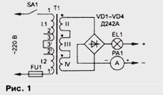
Among the secondary windings of these transformers have a few designed for voltage 40…60 V and a relatively small current. For the chargers, they useless, but the filament winding for the voltage of 6.3 V and a current of 4.7 And fit. If the transformer has three windings, they should be connected in series and be connected to the bridge rectifier powerful (deationary) semiconductor the diodes (Fig. 1). The charging current limiter can successfully serve automotive lamp voltage of 12 V power from 50 to 150 watts.
To obtain the desired power multiple lamps are connected in parallel. When normal charging current of the lamp barely lit, their intensity can be judged the charging current, and the voltage drop across them is small. This limiter protects the device from the circuit or from the battery is connected in reverse polarity - when this lamp is brightly lit (and the reverse polarity batteries often burn out). If you put the lamp 26 and In even greater power, "the fool-complete - the lamp will be damaged and return the battery is connected to on the network device.
The situation will be worse when the filament windings on the voltage of 6.3 V and current 4,7 And will be only two, as, for example, the transformer TC-180-2. When a series connection will receive a total of 13 V. There can be no limiter the charging current is barely enough even with direct connection the battery with the output of the rectifier bridge. It is advisable bridge collected on silicon and germanium diodes, for example, D305. They have less forward voltage drop (0.3 V instead of 0.7), and therefore the charging current will be more. It can bring up to 5 A, boosting mode of the primary winding as charging the battery. Nevertheless, the power transformer in this case used only by one third. To make this transformer charger a device with a current of 10…15 A (and this current is allowed to begin charging batteries with a capacity of 40…50 Ah), it is necessary to wind a new secondary windings. It is not a difficult thing to do.
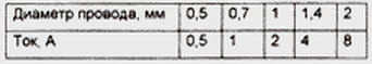
Many stops the absence of large diameter wire for the secondary winding. Indeed, the large current needed a thick wire (see table).
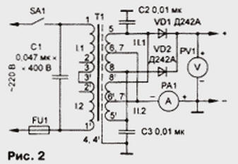
But you can the success to do with what you have, using the winding in a few wires. If to reel push-pull winding for the rectifier according to the scheme of Fig. 2 three wire and to connect two such windings are placed on the two transformer coils in parallel, the required diameter of the wire for a 15 amp device will be only 0.8 mm, in order To expedite the work the two halves of the winding on each coil you need to reel in six wires. The number of turns of the secondary winding - 2x46.
The technology here is this: freeing the coils of the windings, in addition to its primary external insulation is wound trial 46 turns, to find the length of the wire, and measure six segments of the desired length. Solder the findings of the three wires to the petals frame, the winding is wound, making sure the wires are not perelistalis. When the transition to the second layer stack insulation of cable paper. The ends of the wires, again, soldered to the other two petals of the frame, then the ohmmeter checking to see if I messed up the wires. If done correctly, small the resistance will be only between pins 6 and 8 and 5 and 7.
After collecting the transformer and connecting the common wire medium the terminals of the windings on the two coils, it is necessary to determine which extreme conclusions to connect together. For this include a transformer in the network and the AC voltmeter (avometra) measure the voltage between the end terminals of the windings on different coils. Join together those between which the voltage is zero, then connect to the anodes of diodes. Incorrect connection will be a short circuit. Be guided by the pin numbering in Fig. 2 must be with caution because it is unknown which way you wound the coils, and depends on the phase voltage.
In conclusion, a few words about the suppression of noise penetrating from the network. When the transformer is made only for the charger, used in the garage, the interference problem you don't care and screens from a thin foil placed between primary and secondary windings can be deleted. If working the device will connect radio receiving equipment, screens better to keep and their findings (4 and 4') to connect a common wire. Capacitor C1 filters high frequency noise induced from the network. For additional protection are capacitors C2 and C3, shunt high frequency secondary winding. Their the capacity can be in the range of from 0.01 to 0.5 UF. Paper capacitors here a noticeable inductance of the findings, it is better to use ceramic.
Described charger is suitable even for high power radio 100 watts, consuming up to 20 A at a voltage of 13.6 V. In this is the case, the car battery is not disconnected, it performs the function of buffer battery. Connections are shown in Fig. 3.
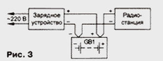
To connect the transceiver and battery (GB1) to the rectifier charger separate wires in any case it is impossible, as will increase the ripple of the supply voltage due to the finite resistance of the wires. At the same recommended turn on not even require smoothing the oxide capacitor. If you still want to put it, to be as close as possible to the power socket the radio station.
Author: V. Polyakov, Moscow