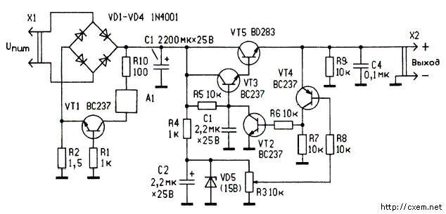
Audible alarm allows the user to quickly react to an emergency situation, if you experiment with different equipment have any overloading of the power source. The scheme of the power source of the stabilizer shown in the figure.

The rectifier diodes VD1-VD4 is powered by a transformer, the secondary winding of which is designed for a voltage of 18 V at a current of at least 1A. Adjustable voltage regulator transistors VT2-VT5 well-known scheme.
Variable resistor R3 to the output can be set to the voltage from 0 to +15V. The detector, designated as A1, is an acoustic frequency generator, connected to an acoustic radiator (speaker, piezo oscillator, etc.). Its schematic diagram is provided as a designer can choose more acceptable to him "sound" (tonal frequency, siren, multi-tone trill, the melody, the simulator different sounds). On the diagram of the device Manager shows only the operation key on the transistor VT1.
The load current of the test (EUT) passes through the resistor R2, creating it the voltage drop. While the current is small (at the selected value of this resistor is not more than 0.3 (A), the transistor VT1 is closed. The increase in the current consumption (and thus increase the voltage of the voltage across the resistor) transistor approaches the threshold of the opening.
When the voltage between the base and the emitter VT1 will reach 0.7 V, it opens and with a further increase of the current goes into the saturation state.
When the lid of the transistor rectified voltage is supplied to the acoustic detector and enables it.
Transistors BC237 interchangeable on CTV, BC327 - CTB, BD283 - CTA. Instead part no 1n4001 diodes suitable rectifier diodes CDB or bridge CCE. As the Zener diode should be used CSA. The power dissipation of the resistor R2 is taken with some reserve, for example in 1W.
Publication: www.cxem.net


