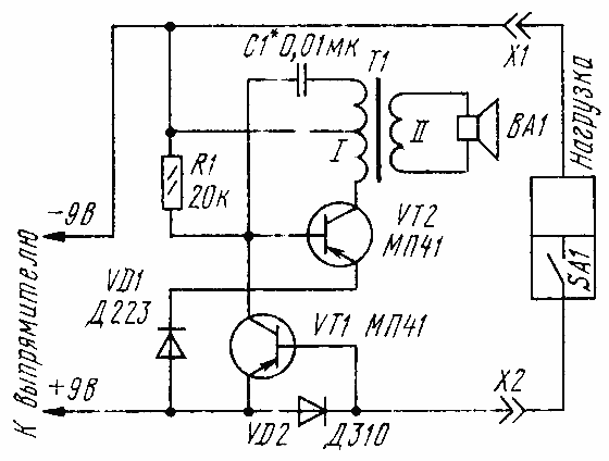
Portable radio, tape recorder or other the device in stationary conditions, receive electricity from the block power connected to the lighting network. Thus there is a risk, leaving the house and turning off the receiver, tape their own switch, leave under voltage the power supply. If it is damaged in your absence, the damage can be quite large. To protect yourself from such trouble will help sounder, whose scheme is shown in Fig. 1.
Transistor VT2 and the transformer T1 is assembled by the scheme of inductive treatacne the oscillator frequency audio. The capacitor C1 together with the primary winding of the transformer determines the pitch played a dynamic head BA1. The operation of the oscillator manages the cascade transistor VT1, whose transition collector-emitter connected between the base of transistor VT2 and a plus power supply. Diode VD2, connected in parallel to the emitter junction of transistor VT1, is in the power supply circuit of the load. Another diode VD1 is in the emitter circuit of the transistor VT2.
When the load is turned on, current flow creates the diode VD2 voltage drop, opening the transistor VT1. As a result the voltage at the base of transistor VT2 is positive relative to emitter defined by the voltage drop across the diode VD1. Thanks this transistor VT2 is closed and the indicator is "silent."
If the load off their switch (SA1), the current through the diode VD2 and the voltage drop is gone, the transistor VT1 is closed. Kicks in the oscillator, from a dynamic head BA1 beep, reminding disconnect the power supply from the network.

Fig. 1

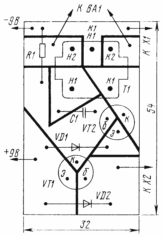
Fig. 2
In the detector, except indicated in the diagram, can to use other transistors series MP39-MP42. Transformer T1 is output from the receivers Selga 404", dynamic head - 0.1 DG-8, 0.25 DG-19 or other compact voice coil impedance of 8...10 Ohms. Instead of the diode VD1 will fit any silicon (series D226, D), VD2 is better to use germanium, for example, series D load current up to 50 mA, DA at load currents up to 80 mA or D at higher current. The capacitor C1 may be MBM, KLS, resistors MLT, MT capacity from 0.125 watts.
Details of the detector well be mounted on a printed Board of foiled fiberglass (Fig. 2). Thick lines in the drawing, denoted by the slits in the foil, the insulating printed conductors from each other. Of course, payment can be made by etching, but then ferric chloride.
The establishment of the generator is reduced to the selection of the capacitor C1, which determines the tonality of the signal. You may also need clarification of the resistance of the resistor R1 to provide a clear run the generator.
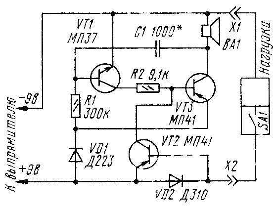
If you will not need a transformer, the device may be assembled according to the scheme shown in Fig. 3. On transistors VT1, VT3 different patterns are made asymmetrical multivibrator, the oscillation frequency is changing the selection of the capacitor C1. The sound projector serves as a driver or electromagnetic earpiece.
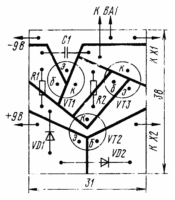
Transistor VT1 - any of the series MP-MP, other the details are similar to the previous version. Are they are on a circuit Board in accordance with Fig. 4.
Any of the detectors should be strengthened on common ground with the power supply.

Fig. 3

Fig. 4
Author: Yu Prokopcov, Moscow; Publication: www.cxem.net


