


")

Sometimes to power various electronic devices you want to have two bipolar voltage of +12 and -12 V (or +9 and -9 In) from one source - battery or mains transformer with one winding. Such the voltage required for operation of operational amplifiers and some other schemes. While the current consumption of the circuit is usually in circuit with the positive voltage, and the circuit "-" is a subsidiary.
The industry produces a specialized chip Converter for receiving a negative voltage: CRAP (input voltage 3…10 V, and the output is negative with the same magnitude as that of the input. But it is not yet widely available, and covers a narrow range voltages.
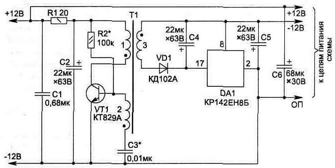
Fig. 5.4
In Fig. 5.4 shows a diagram of a simple inverter, which allows you to get from the source +12 (+9) more stable voltage -12 V (-9 In with stabilizer CREA). The load current the chain-12V can be up to 15 mA.
The Converter operates at a frequency of 50 kHz and stores its efficiency by reducing the voltage to 7 V.
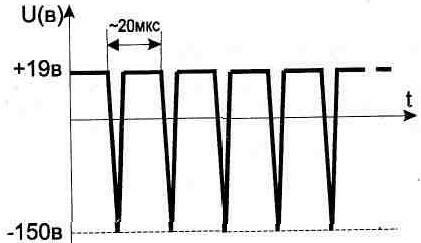
Fig. 5.5
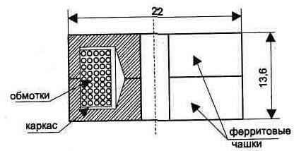
Fig. 5.6. The design of the transformer T1
The scheme consists of an oscillator transistor VT1, increasing the voltage of the transformer T1 and integral stabilizer DA1.
When the Assembly is required to comply with the polarity phase windings of the transformer T1 shown in the diagram. From the secondary winding of the transformer the voltage after rectification should be 15…19 In that it is necessary for normal the stabilizer operation DA1.
To configure the Converter first, instead DA1 the plug 150 Ohm resistor. During normal circuit operation waveform on the winding 3 of the transformer T1 shown in Fig. 5.5, When tuning may be required selection of the capacitor NW and resistor R2.
Transformer T1 is performed on an armored core size B ferrite 2000NM (NM) and contains in the winding 1 - 80 turns 2 - 15 turns, 3-110 turns of wire PELSHO-0,18 (Fig. 5.6). After checking and scheme settings, coil and ferrite Cup secured with glue.
Capacitors C2, C4, C5 applied type K50-29-63V, S1 and Sz - any small, C6 - K53-1A-20V.
All circuit elements are placed on a printed circuit Board with dimensions h mm (Fig. 5.7). To reduce the height of the Board mounting is made in two levels - the capacitors C4 and C5 are located above elements VT1 and DA1. Scheme allows to obtain a higher output voltage than the input, if you use negative release voltage (Fig. 5.5).
If you've collected is a stationary device and can be powered from the network, it is possible to obtain a bipolar voltage can be applied widespread small-sized transformers (structurally designed in view of the plug). They have one secondary winding, and not to rewind transformer, it is convenient to use the scheme (Fig. 5.8).
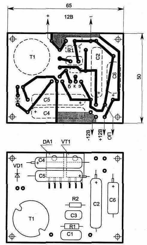
Fig. 5.7. PCB Converter
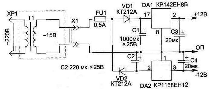
Fig. 5.8
Publication: www.cxem.net