


")

To supply some of the sensors required Micropower high-voltage source. Converter (Fig. 5.31) allows you to teach a stable voltage, set within 100…700 V, when the current in the load to several tens of microamperes.
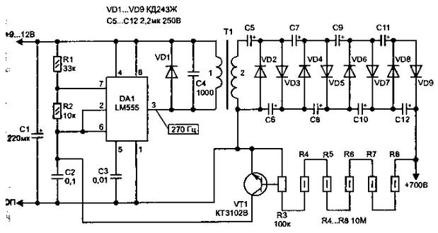
Fig. 5.31. Circuit high voltage stabilized power supply
Generator, assembled on the timer operates at a frequency of 270 Hz. As increasing the voltage of the transformer T1 is used to network with the winding on 6.3 In a current capacity 280 mA (winding 1) when the voltage in the primary coil (2) 220 V. In this case, when shown in the diagram to enable the winding 2 will be 100 V. This voltage is rectified and multiplied by the diodes VD2.VD9 and the capacitors C4 C12....
Transistor VT1 is made stabilizing feedback. Using collected on the resistor R3.R8 voltage divider, the signal output from the source is supplied to the base transistor VT1. Output voltage regulation is performed at the expense disruption of the operation of the generator in excess of a predetermined level (when the transistor opens - it short-circuits the capacitor C2). The level of stabilization depends on the provisions of engine tuning regulator R3. For ease of configuration R3 have to be reusable.
Author: I. P. Shelestov