Most network power sources (adapters) for powering portable equipment in the home are simple circuits consisting of compact power transformer, rectifier bridge and of a capacitor of 1000 µf.
More complex contain adjustable voltage stabilizers. But almost no adapters with built-in timers, but it would be very convenient, because often adapters are constantly plugged in, regardless of work load or not, Yes and the load, for example, radio, you can forget to turn off. Here it's not even excessive consumption of electric power (adapter consumes little), and fire the danger is particularly relevant in the hot pet, when literally all equipment melts. Plus, the ability to use power supply as a timer.
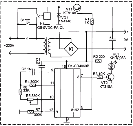
The figure shows the scheme supplements the normal power supply by a timer, which you can use smoothly (variable resistor) to set a time ranging from 10 minutes to 2 hours, after which the adapter will power off completely, unplug it.

The scheme is not marked in detail, it's the details of the network adapter, they are few power transformer, bridge rectifier and electrolytic capacitor, adapter, China, are made of a large plug, to provide constant a voltage of 9 V At a current of 350 mA (according to the inscription on it) in the gap of one of the conductors of the primary winding of the transformer included the start switch S1 and the relay contacts K1. If you are not going to use the timer - switch S1 and use the AC adapter as usual, the circuit of the timer it will not have any influence.
To use the timer, you need to enable the adapter to the network as usual, then turn on and off S1. After that will start the countdown, and then the adapter will turn off completely. Accordingly turns off and the load.
Diagram of the timer done on the basis of chip CD4060B.
At the time of inclusion power by means of a chain C1-R7 happens a forced reset of the counter IC D1. Zero its MSB is supplied to the base of transistor VT1 and opens it. In the collector circuit of the transistor included turnips K1, it closes the contacts. Now if you turn off voltage S1 the primary winding of the transformer will flow through the relay contacts.
From the moment you turn the countdown begins installed AC resistor R5. Resistor R5 is governed by the frequency of pulses generated built-in RC multivibrator circuits CD4060. Internal circuits of the chip the pulses arrive at the binary 14-bit counter. Some time later, that depends on the frequency of pulses (counting 8192 pulse), at the senior exit counter (pin 3) appears logical unit. Transistor VT1закроется and the relay K1 will shut down your contacts. The scheme will disconnect from the network completely
HL1 led - to indicate the enabled state. He blinks, and the more the preset shutter speed time, so it blinks slower.
Electromagnetic relay type TRG5-9-VDC-FA-CL in a small package sizes just 12x8x10 mm (such relays are used in some computer modems). Contacts rated current up to 0.25 A at a voltage of 230 V. it is Possible use another miniature relay with parameters not worse than these.
No domestic alternative to chips CD4060B does not exist. However, it is possible to assemble the circuit of the timer on IC CIE, CIE or CPS, but of course, the scheme will differ, as these chips are not direct analogues CD4060B.
The figure shows a scheme of alterations simple 9-volt adapter without adjustment of the output voltage. In practice more often universal adapters, which from the secondary winding of the transformer is made bends, a toggle switch. In this case, the scheme should be added to this one bridge rectifier, which is connected to the outlet when connecting to which additional output of the rectifier bridge is the voltage 10 8... V. So also, it will need an additional blocking capacitor 470...1000 µf, you want to connect the output of the additional rectifier bridge.
Author: Tarasenko V. I.


