The laptop is definitely a handy thing, but the problem is that the charge of his battery lasts usually for an hour or two or three. It's not enough. Quite reasonably, moving by car to nourish and charge the laptop from the car side network. But, for some inexplicable reason, the voltage of the most laptops 19th Century, Frankly, is a very strange figure.
The output can be only one, is to make the DC-DC Converter that increases the voltage of the car battery to 19 Q. Now, there are many schemes for DC-DC converters, by changing the ratio of resistors of the divider measuring the voltage which you can get different output voltages, from units volts to 30...50 V. not claiming originality, I want to share scheme his self-made DC-DC Converter to power the laptop.
The Converter can be powered with a voltage of 10 to 15 V, output 19 V At the maximum current of 2.5 A. There is a scheme undervoltage protection input voltage below 10 and In overload at the output.

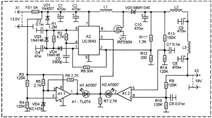
The controller pulses the change of duty cycle is executed on specialized chip UC3843 (A2). The scheme is almost typical. Output pulses arrive at the the shutter powerful key field-effect transistor VT1. Conversion occurs on a frequency of about 50 kHz. Pumping voltage occurs across the inductor L1, the Rectifier is formed on the diode Schottky VD5. Ripple smoothing first, C10. Then should the two filter inductors L2 and L3 and the two capacitors C9 and C8.
The magnitude of the output voltage is set by resistors R11-R12. They form a voltage divider, the ratio of the shoulders which should be such that when the required voltage at the output, at pin 2 A2 voltage was 2.5 V. When indicated on the diagram the values of the resistances R11 and R12, the voltage at the output will be stably be maintained at 18.75 per Century since real resistors always scatter of the values, when establishing the value of R11 (and maybe R12) should be selected so that at the output a voltage of 19 V. This can be done including in parallel with these resistors significant additional resistance greater magnitude. On the circuit Board has a track under them. Including the resistance R11 in parallel, we reduce the output voltage, and in parallel R12 - increase the output voltage.
Diode VD1 helps to burn out the fuse FS1 in case of improper filing the input voltage.
On dual operational amplifier A1 is made of the protection scheme. At the shelter A1.1 - the scheme of measurement and control of the input voltage. While the input voltage is above 10V the voltage at the inverted input of A1.1 more than direct.
The output is zero, the led D1 turns off, and the A2 pin 3 voltage lockout generator is not supplied.
If the input voltage decreases, the direct input of A1.1, the voltage becomes more than the inverse. - the output voltage of the unit, the led D1 is lit, and generator A2 is blocked. If you want to change the threshold of lock you can pick up the resistance of the resistor R3 or R4.
The second AW A1.2 measures the output current.
Measuring resistance are winding coils L2 and L3. In case of overload the voltage at the direct input of A1.2 will be more voltage at the inverted input. On the output of A1.2, there is a voltage units. The led D2 lights up and through him on the A2 pin 3 enters a blocking voltage.
The threshold depends strongly on the active resistance of the coils L2 and L3. The threshold in the process of building put up by selection of the resistor. R13. As it decreases, the operating current is reduced, while increasing - increases.
Coils are wound on a ferrite rings. Coil L1 is wound on a ferrite ring an outer diameter of 23 mm., It contains 60 turns of wire sew 0,61. Coils L2 and L3 wound on a ferrite rings outside diameter of 16 mm. They contain 120 of turns of wire sew 0,43.
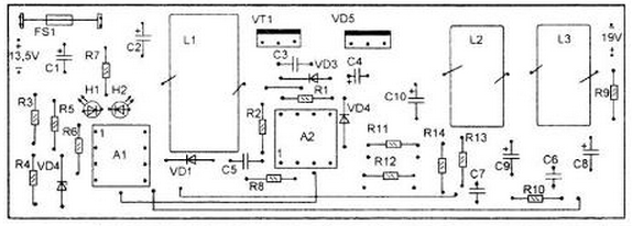
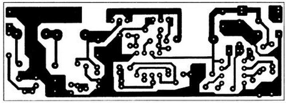
All assembled on a single printed circuit Board.


The fee is compact, so the details must be miniaturized. The fee is one-sided, there are some jumpers, mounting wire.
Coils L1-L3 mounted vertically. Initially they are holding their own conclusions, and after establish they are glued to the Board with epoxy glue.
All capacitors must be rated for a voltage of less than 25 V.
The 1N4007 diode can be replaced by CD or even exclude from the scheme, but in this case, when polarity of the input voltage can be damaged before the fuse FS1.
The 1N4148 diodes can be replaced by KD522.
Author: V. We Can Say


