Power supply Toshiba laptop-Satellite 19 is at maximum In the current of 3 A. Unfortunately, it is not suitable to work in the car, as there is 12 V.
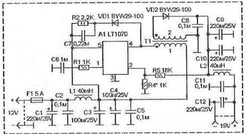
The figure shows a diagram of a voltage Converter that increases automotive 12 V to notbecause 19 In, and support this voltage stable. The circuit is based on DC-DC Converter on the chip LT1070.

The voltage from the electrical system of the vehicle via a 5 amp fuse and poljoprivreda circuit enters the power point circuits A1 (pin 5).
Generator chip starts working and feeding the pulses to the key available on A1 connected between the pin 4 and the negative (pin. 3).
The key periodically opening pulse current passes through the primary winding the transformer T1. The secondary winding of T1 is induced alternating voltage is rectified diode VD2 and smoothed capacitances C9, C10.
Further, through the chain L2-C11-C12 DC voltage 19 To appear on the output source.
To control the level of the output voltage and its stabilization is used internal circuit A1. The essence of her work that she so changes the duty cycle supplied to the primary winding of the transformer, so at pin 2 A1 was a constant voltage of 1.24 V.
The date of obtaining a stable output voltage from the secondary output the rectifier on the DC voltage VD2 through the divider to file for output 2 A1. The ratio of the resistor divider must be such that when properly the voltage at the output, at pin 2 A1 a voltage of 1.24 V.
Accurate selection R4 set the desired nominal stable the output voltage. In this case, it is the 19th Century For winding of the transformer is taken the ferrite ring external diameter of 32 mm ferrite 2000NM. The ring wrap a thin layer of fluoropolymer film or varnished cloth. You can ring no wrap and cover with a layer of epoxy puck. After it dries you can wound windings. It is possible that for winding of the transformer can to use the ring of different diameter and ferrite materials - you need to experiment.
The primary winding has 40 turns of the winding wire, consisting of two together, sew the folded wires 0,43. You can use a single wire cross-section of 0.9, but will be more difficult to wind the Secondary winding contains 70 turns the same double wires. First primary winding is wound, and then on her the secondary surface, stacking wire in the same direction as the wound the primary one. At the start winding circuit of the transformer marked points.
For chokes are used rings with a diameter of 18-20 mm. They contain 30 turns the same double wires, as for winding of the transformer.
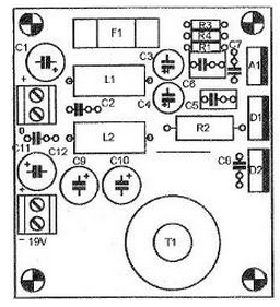
Converter circuit assembled on a printed circuit Board with unilateral location print tracks.

Chip and diodes should be strengthened on the radiators. Common radiator can to be a metal housing, which is assembled Converter (diodes on the Board and the chip is specifically located at the edge). The chip can be installed on radiator-housing using heat conducting paste, without isolating, as it the radiator plate is connected with the 3rd output, a negative (ground). And the diodes on the heatsink need to be put through the mica strip for heat-conducting pasta, using ebony washers, to provide isolation of the cathode plates from the housing.
With proper installation and operational details of the establishment is just to check the output voltage. If it is necessary you need to change the resistance of the resistor R4. The decrease in resistance leads to increased voltage, and an increase to his demotion. Surgery replacement of resistor you need to do only after the power is turned off. Therefore, it can temporarily replace variables resistance 1.5...2.5 kW. With it, you need to install the required output the voltage check on the load, for example, by connecting the pampas filament 36 In (or two series-connected automotive bulbs for rear lamps).
After setting need to be completed after the power is turned off, unsolder variable resistor and measure its resistance. Then install it on cost fixed resistors such resistance or very close to obtained. Maybe denomination you will not have and will need to recruit R4 of several resistors using serial or parallel the inclusion.
To turn on the transmitter without heat sink under the chip A1 is risky, so, even in the process of building, especially when tested on the load, it is necessary to install its a radiator and periodically monitor the temperature.
The same transducer can be used to power other devices from the vehicle network. The desired output voltage set selection resistors R5-R4 and the number of turns of the secondary winding of the transformer.
Author: L. Kuzenski


