


")

Here is the schematic diagram of digital DC voltmeter built based IC ICL7107. The power supply for this circuit is +5V. You may use 9V battery and then use regulator IC LM7805 to achieve 5V stabilized voltage. This circuit will be good to display your power supply output.
Components List:
R1 = 8K2
R2 = 47K / 470K
R3 = 100K
R4 = 2K
R5, R6 = 47K
R7 = 0R / 4K7
R8 = 560R
C1,C5, C6, C8, C9 = 100n
C2 = 470n / 47n
C3 = 220n
C4 = 100p
C7 = 10-22u
D1, D2 = 1N4148
IC1 = ICL7107
IC2 = NE555
OPTO = CA 10 pin
Top PCB Layout:
Bottom PCB Layout:
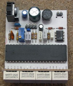
Constructed Circuit:
This is the another DC voltmeter circuit design which show you about how to make reading scale. It is just need rotary switch and some resistors with different value at the input/measurement point.
source: http://www.reber.si/dvm/index.htm