A large proportion of the units of series Panasonic KX-F50 is cheaper modification designed for a mains voltage of 120 V (frequency of significant does not matter). One of the reasons of failure of these devices is their the inclusion in the mains 220 V without step-down transformer. As a result there is a need to repair. Power supplies model KX-F50B (220 V) befalls the same fate due to voltage spikes in the network. In addition, even with proper power supply is often found fault with some of his elements that may lead to the disappearance of the apparatus of the functions of printing in mode copy and Fax reception.
Fax machine Panasonic KX-F50 is the basis for subsequent models - KX-F60, KX-F90 and KX-FUO, they all have similar power supplies. Structural scheme such a block is shown in Fig. 1.
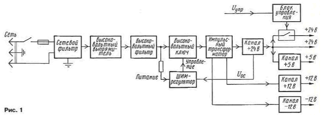
The power supply voltage through the switch and network the fuse is supplied to the surge protector to prevent impulse noise from the operation unit in the network, and then rectified by a high voltage rectifier. The rectified voltage ripple smoothing filter.
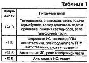
The filtered DC voltage is supplied to the high voltage key and using the quenching resistor in the power circuit is a PWM controller that controls key. The voltage pulses from the output of the key is received by the pulse step-down a transformer. The voltage taken from the secondary windings is rectified, filtered and further stabilizes the relevant circuits. Main consumers are listed in table. 1.
Upper circuit channel power supply supplying voltage of +24 V is to power the thermal head. Them manages a special device on a signal from the CPU of the facsimile apparatus.
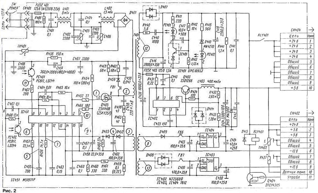
Schematic diagram of power supply unit KX-F50 shown in Fig. 2.
(click to enlarge)
The image the schema is as close as possible to how it is given in the foreign literature. Model KX-F50B differs from it mainly by the values of some elements (for this option, they are noted in parentheses). Note that there may be differences in depending on the year of manufacture of equipment.
AC mains voltage comes through the noise filter, consisting of elements S, 1.401. L402, S-S. rectified by a diode bridge D401 and smoothed by a capacitor C. Varicore S and S function protection against transient voltage spikes (if a third wire the power cord of the Fax machine is grounded). The thermistor TN prevents inrush current when the device is in the grid.
On the chip IC451 assembled PWM controller. The conversion frequency is approximately 120 kHz. Output voltage control is made by the method pulse width modulation (PWM) by changing the duration of the open the state of the pulse key Q405 with accumulation of energy in the core of the pulse transformer T.
The signal of the output voltage at the output of the off channel +24 V. feedback provides optocoupler RS. The voltage sensor is a precision divider R412R413, the voltage from which is applied to the regulator IC401. In Fig. 2 chip regulator is shown simplified. More details about it will be told below. When increasing the output voltage of the power supply voltage in secondary the point of the divisor exceeds exemplary, the transistor opens, the current through the led the optocoupler RS will increase, the phototransistor of the Photocoupler RS opens and the pulse duration at the output of the PWM controller will decrease.
When there is an excess of output voltage source +24 V (for example, when the output of the operating mode at startup) opens the Zener D410. current through the led of the optocoupler RS increases, the phototransistor RS open, the frequency of the master oscillator, the PWM controller is reduced.
Voltage +5 V is formed from the voltage +24 V transmitter on a chip IC402, also operating on the principle of PWM regulation. The work of the +12 V and -12 V linear regulators provide IC403 and IC404 respectively.
The thermistor T is located on the heat sink of the power supply. When copying completely black document for a long time or overload, caused by any other reason, there is overheating of the heat sink. The resistance of the thermistor T decreases with 25 kω (25°C) up to 2 ohms (85°C). The signal from the thermistor is converted into digital form by the ADC PA chip IC201, located on the main Board of the Fax machine, and read by the CPU of the device. In case of emergency the situation is software lock.
On-Board power supply relay is located RLY401 that the command processor applies a voltage of +24 V to the thermal head when you enable copy mode document or when you receive a Fax message. In these modes at pin 11 connector CN402 there is a high logic level, transistor Q404 open, relay RLY401 is actuated, its contacts are closed and the voltage of +24 V is supplied to the thermal head.
Elements FB1, FB6, FB7 represent chokes with a small inductance, educated ferrite tube worn by the conductor. Their purpose is suppression of high frequency noise on the voltage pulses generated at the time transfer the accumulated voltage from the secondary winding of the transformer to the load when closing the power switch the PWM controller.
Connector CN404 thermal head is connected to the connector CN402 Plata Fax of the apparatus.
Waveforms at various points of the power supply unit shown in Fig. 3.
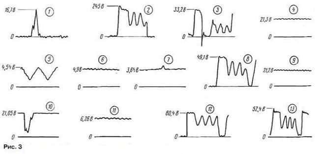
Period all pulses is approximately equal to 8 μs. All waveforms except 8, 12. 13. removed regarding point A, which is common to the primary circuits of the power supply and is galvanically connected to the grid. For this reason, the case of the oscilloscope is not must be grounded, and the power supply is better to include in the network (at the time measurements) via an isolation transformer with a transformation ratio of 1:1.
As practice shows, the main elements of most frequently emerging from system, are fuse FUSE 401, a diode bridge D401, capacitor C, power transistor Q405, IC-PWM controller IC451, varistors S, S.
Faulty power supply is removed from the housing after removing upper rear cover part of the apparatus. Repairs start with a visual inspection of elements. Malfunction varistor and capacitor C can be determined by swollen buildings. Released down varistors better to remove from the Board and not to replace, as their effectiveness as protection elements raises some doubts. In block supply, 120 V, diode bridge D401 can be replaced by four diode KDA. collected mounted Assembly according to the scheme of the rectifier bridge.
After replacing faulty elements in parallel with the capacitor serves S voltage 18...30 V from an external source and an oscilloscope to check the availability the control pulses to the gate of the field-effect transistor Q405. If absence will require replacement chip IC451. You can then close shorted resistor R454 and check for pulses on all windings transformer, checking the waveforms and making allowances for the fact that the input the power supply voltage does not exceed 30 V. If the forms of all waveforms in normal, you can safely enable the power supply to the grid or to an external source high voltage, by connecting the pre-load resistance 5... 10 Ohm to the output of the channel is + 5 V. After that, check the voltage at the output of the block power. If everything is OK, the PSU is mounted on the seat.
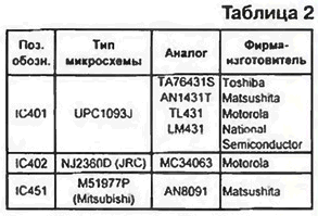
The main chip power supply manufacturers and their counterparts of other chips firms are given in table. 2.
Chip IC403 and IC404 - linear 7812 voltage regulators, manufactured various manufacturers (domestic analogue - CREB).
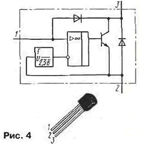
Chip IC401 is an element, called in foreign literature three-electrode diode shunt regulator. This monolithic IC source reference voltage, equivalent circuit which is similar to the Zener low temperature coefficient of voltage stabilization (Fig. 4). It can be used as an analogue of the Zener diode with adjustable (using two external resistors) voltage stabilization from about 2.5 V to 36 V and a current of stabilization of from 1 to 100 mA. Home analog KREN (see "Radio". 1994. No. 4. p. 45. 46).
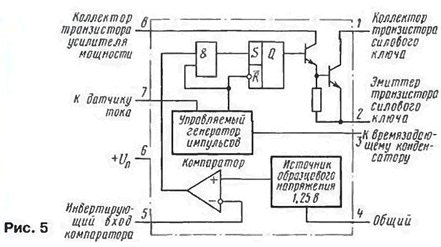
Chip IC402 controls the DC-DC converters in constant (DC/DC) based on the PWM. The chip (Fig. 5) contains an internal thermocompensation the reference voltage source, comparator, controlled a generator device limits the duration of the pulses during the occurrence of overcurrent, buffer amplifier and a power output key.
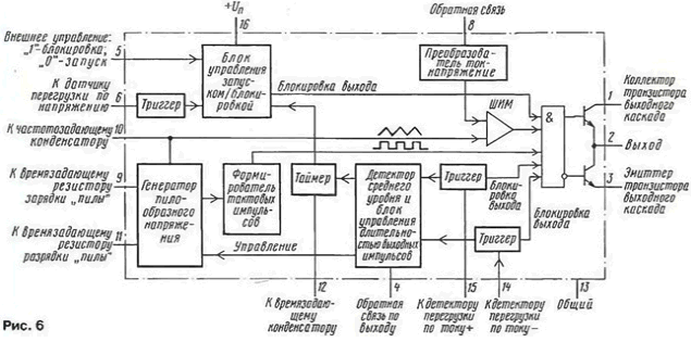
IC451 - IC for switching power supplies based on the PWM with integrated overload protection as current and voltage, with the possibility of external control run/lock (Fig. 6). It can be used as A PWM controller with a conversion rate of up to 500 kHz.
MOSFETs used as high-voltage key supply A (2SK1357 - for modification of 220 V and 2SK1488 - for 120 V), and field. MOS structure with an n-channel. working in the mode of enrichment.
The main parameters are given in table. 3.

Author: S. Ryaboshapko, Odessa, Ukraine


