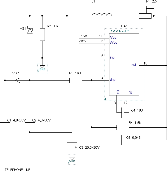
The scheme is an amplifier with positive feedback. Mounted on t/f line parallel to the modem. Strengthening 1,5..2 times. Operational amplifier DA1 is possible to use any given pin. 553ud2 used in plastic DIP. 3 +Vcc=9...15V, -Vcc=-9...-15V. Ie need a bipolar source with an average "ground" (gnd). L1 - any choke at 200..400uH. DP1,2-400 used. R1 adjusts the gain. VS1, VS2 - symmetrical Zener 20V to protect DA1. Used 2 series-connected XB. Capacitor C3 is enabled correctly: (+) to gnd.

Setting
If you have an oscilloscope, while the power is on and connected t/f line (pipe up!) checked for generating at pin 10 DA1 at the left on the diagram the position of the R1 engine.
Increase increasing R1 failure to achieve generation. This position R1 corresponds to a threshold level of amplification. To add stability 5..20% of the current value of R1.
All these operations can be done without an oscilloscope at the hearing, connected in parallel with the device, but will need to consider the additional load on the line. The final position of R2 for a particular connection.
Publication: www.cxem.net


