


")

Time tracking telephone calls using special counters. The apparatus differs from that previously described in that it takes into account the time for talking is over precisely as it analyzes the signals on the telephone line.
The principle of hourly pay local telephone calls involves the payment of only those calls that originate from the subscriber. Thus some limit your talk time is available in the account monthly a fixed fee. Naturally, users of the telephone network and interesting good to know your "spoken" to, for example, time to move on mode "informal economy" or rate at the end of the month additional costs.
The algorithm of the device explains the functional diagram shown in Fig. 1.
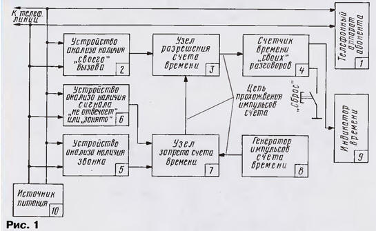
In the presence of a call signal (call) unit 5 generates and outputs the control the voltage at the node of the ban time accounts (unit 7), which in this case breaks the chain of the passage of clock pulses. The time indicator (unit 9) displays the previous testimony without modification. At this time missing regardless raised the subscriber up your phone or not.
When you pick up the handset of the subscriber device is triggered analysis of the availability of "their" call (block 2) and prepares a circuit for the passage of clock pulses through the node resolution time accounts (unit 3).
The necessary conditions of passage of clock pulses from the generator (block 8) through node ban (block 7) are the lack of a calling signal before picking up the handset and the end signal "not responding" after dialing the subscriber. Thus, the account occurs only when held outgoing connection. In the case of the busy signal, the account also will not start.
The current call is displayed on the indicator time (block 9). Unit 4 operates in the accumulation mode. To reset a button "Reset". Power to all elements of the device can be powered from a power source (block 10), which, in turn, is powered by the telephone line.
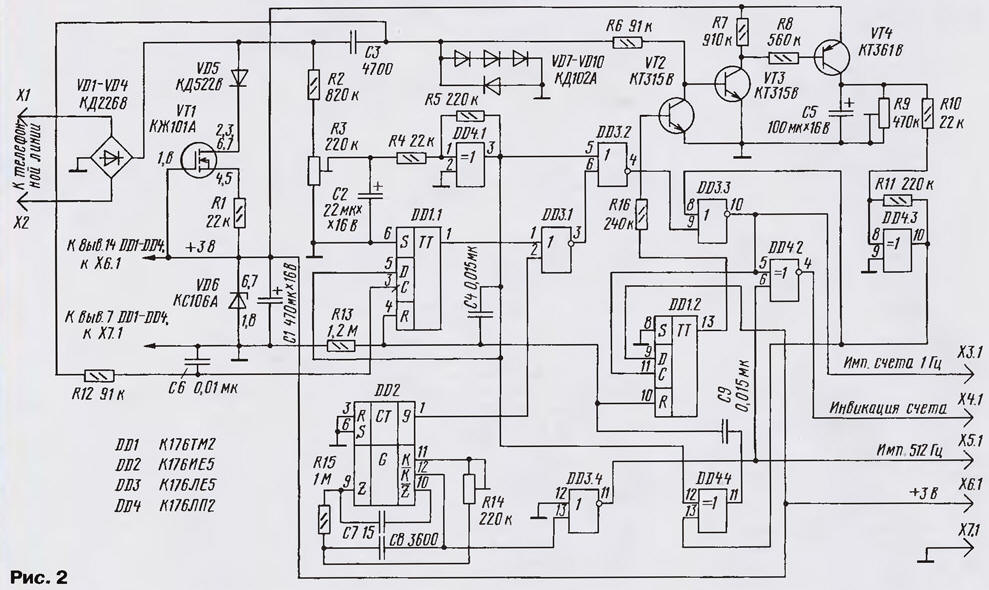
Schematic diagram of the device shown in Fig. 2. The pulse generator account assembled on a chip DD2. The peculiarity of its construction is the absence, for simplify, quartz resonator used in the standard circuit diagram. On the output 9 of the chip DD2 (pin 1) are the clock pulses with a frequency of 1 Hz, and output - pulses with a frequency of 512 Hz, which are used for LCD HG1 & presentation counters DD5-DD10.
(click to enlarge)
(click to enlarge)
The unit of analysis of the availability of the call works as follows. Ringtone (AC voltage with a frequency of 25 Hz and an amplitude of up to 110 In) from the line through the capacitor C3 is supplied to the diode limiter VD7-VD10. Applied the inclusion diodes allows you to convert a sinusoidal voltage of a call in almost rectangular pulses with an amplitude of 2.1, that switch trigger DD1.1 input C. as the input D of the flip-flop DD1.1 at this point, there is a high the level of the output element DD4.1, the direct output DD1.1 also appears high level. This signal prevents the passage of clock pulses through the element DD3.1, which come with chips DD2. If the subscriber picks up phone for conversation, time accounts will not happen.
When hook subscriber switch the Schmitt trigger on the element DD4.1. At its input signal from the divider R2R3. In this case, happens the level change from high to low, but with some delay, due to the presence of the capacitor C2. The capacitor C2 is required for filtering out signals dialing, call and interference that could lead to a false trigger DD4.1. Low level output DD4.1 is fed to the input D of the flip-flop DD1.1 (which now will not alter the original zero condition, regardless of any signals at the input, if not it was a call) and the input of the DD3.2, which permits the time.
From the output of DD3.2, the clock pulses arrive at the element DD3.3, to the second input (conclusion 8) control level fed from the output of the device for analysis the presence of signal "not responding" (parcels sinusoidal pulses with a frequency of fill 425 Hz, duration of 1 second and pause 4 (C) or busy (similar parcels with a pause of 1 second). The pulses are differentiated in the diode VD7 - VD10, amplified transistors VT3, VT4 and charge the capacitor C5 is almost to the voltage source power. During the pause, the capacitor C5 is discharged through a trimmer R9. The transistor VT2 is at this time closed. Resistor R9 installs time constant to within 4 with (pause) switch Schmitt trigger DD4.3, which converts the exponential fronts on his entry into cool output.
Thus, while the capacitor C5 is allocated signal "not responding", the trigger DD4.3 is in a single state and its output signal prohibits the passage of clock pulses through the element DD3.3 - at its output a low level. After connecting subscribers of the signal is lost, the trigger DD4.3 switches and low permit the passage of clock pulses through element DD3.3 on connector X3.1 and further to the input of the time counter "their" the conversations. At the same time these pulses arrive at the input of the trigger DD1.2 and the entrance pulse shaper indication of accounts (element DD4.2). The trigger DD1.2 switches and opens the transistor VT2, which bypasses the input device signal analysis. This is necessary to avoid charging of the capacitor C5 speech signals and interference signals in the line.
Zeroing trigger DD1.1 and DD1.2 is a flow pulse generated differentiating circuit C4R13 from lowering the handset on apparatus and transition, as a consequence, trigger DD4.1 in one state. In if the receipt of ringing in the absence of the subscriber (the tube will not be raised) triggers DD1.1, DD1.2 switch the same as in the operating mode, as described above, and may be done by a pulse from the differentiating circuit C9R13 that occur during the switching of the Schmitt trigger DD4.3 in zero the state after the end of the door-bell signals.
Element DD4.4 prevents the resetting of the trigger DD1.1 if the call and picking up the handset, as in this case, the reset pulse from the output DD4.4, occurs when you pick up the handset, is divided in half on the capacitors C4, C9 and the amplitude is not sufficient to trigger DD1.1. Low the level at the input D of the flip-flop DD1.1 (while off-hook) allows the trigger to remain in the zero state when exposed to the chain C3R12 pulse dialing rooms and pulse interference in the line of its input S.
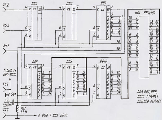
The time counter "their" conversations assembled on a chip DD5-DD10. Frequency of clock pulses of 1 Hz. Counters DD5, DD6 consider the units and tens of seconds, DD7, DD8 - units and tens of minutes, a DD9, DD10 units and tens of hours. Total the time that can count counter to overflow - 99 hours and 59 minutes. Minutes and hours are displayed on the liquid crystal display HG1. Work the device in the counting mode is determined by blinking with a frequency of 1 Hz average decimal point (pin 9 HG1). Set the counter to zero and the indicator is performed by applying the pulse to the inputs of R, generated by the differentiating circuit C10R17 pressing SB1.
The device is powered from the telephone line using Micropower voltage regulator diode VD6, operating current which sets the current stabilizer VT1. Diode bridge VD1-VD4 provides independence from polarity when the device is connected to the line. The current consumed by the device in the standby mode, not more than 100 μa.
Establishing device is easy and comes down to the three adjustment trimpot the resistors. A trimming resistor R3 sets the voltage on the capacitor C2 (hang up) equal to the supply voltage (3 V). On appointment resistor R9 mentioned above. Resistor R14 is set pulse frequency account, which must be equal to 1 Hz (you can control the signal frequency of 512 Hz output To the chip DD2).
The connection is not certified devices to the telephone network common use is prohibited, so the device can be connected only to PBX and similar networks.
Author: I. Zabelin, Moscow