


")

Fragment from Cisco Internetworking Technology Overview. Translation Of Vladimir Pleshakov. Full document can be found on the company's server mark-ITT, http://cisco.udm.ru/ITO.
Bibliographical referenceThe name of the network Integrated Services Digital Network (ISDN)(Digital network integrated services) refers to a set of digital services, which become available to the end users. ISDN involves the digitization of the telephone network for voice, information, text, graphic images, music, video and other material sources could be transferred to Konecna the user via the existing telephone wires and received from one terminal of the end user. Supporters ISDN draw view of the network on a global scale, in many ways similar to today's telephone network, the exceptions that it uses the transmission signal and cyfrowego new variety of services.
ISDN is an attempt to standardize subscriber services, interfaces the user/network and network and firewall capabilities. Standardization subscription services is an attempt to ensure the compatibility level in international scale. Standardization of the user interface/network stimulates the development and sale in the market these interfaces manufacturers, which is the third participating party. Standardization of network and firewall capabilities helps in achieving the goal of a possible outbreak of unity on a global scale by providing ease of communication networks ISDN with each other.
Applications include ISDN high-speed processing system images (such as facsimile Group 1V), additional telephone lines in homes for servicing industry for remote access, high speed file transfer and video conferencing. Voice undoubtedly will become popular application program for ISDN.
Many commercial networks are beginning to offer on ISDN prices below tariff. In North America commercial network connection to the switch LAN (Local-exchange carrier (LEC) begin to provide ISDN as an alternative to the T1 links that are currently vypolnyayut most of the services "global telephone service (WATS) (wide-area telephone service). Components ISDN
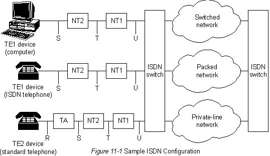
In the number of ISDN components include terminals, terminal adapters (TA), device shutdown network, equipment shutdown lines and equipment completion of switching. There are two types of ISDN terminals. Specialized ISDN terminals are referred to as "terminal equipment type 1" (terminal equipment type 1) (TE1). Terminals not developed for ISDN, such as DTE, which appeared earlier ISDN standards, referred to as "terminal equipment type 2" (terminal equipment type 2) (TE2). The terminals TE1 is connected to the ISDN network via the digital communication line of four twisted wire pairs. The terminal TE2 is connected to the network via ISDN terminal an adapter. Terminal adapter (TA) ISDN can be either a stand-alone device, or channels inside TE2. If TE2 implemented as standalone devices, he connects via THE standard interface physical layer (for example, EIA232, V or 24 V. 35).
The next connection point in the ISDN network, located at outside devices TE1 and TE2 is NT1 or NT2. This device shutdown network connecting the four-wire subscriber installation to the traditional contour of the two-wire local network. In North America NT1 is the device hardware parcels of the customer" (customer premises equipment) (CPE). In most other parts of the world NT1 is part network, provide commercial communications networks. NT2 is more complex the device, which is usually used in "private digital telephone stations with access to a common network (PBX), and performs the functions of the protocols of Levels 2 and 3 and services for the concentration data. There is also a device NT1/2; this is a separate a device that combines the functions of the NT1 and NT2.
In ISDN set a certain number of control points. These milestones define logical interfaces between functional groups, such as TA and NТ1. Reference points ISDN point are "R" (reference point between non-specialized equipment and ISDN TA), "S" (reference point between user terminals and NT2), T (reference point between devices NT1 and NT2) and "U" (reference point between NT1 devices and equipment shutdown line in the commercial networks). Control point "U" is only relevant to North America, where the NT1 function not provided commercial communication networks.
In Fig. 11-1 shows a Sample configuration of an ISDN". Figure shows three devices connected to the ISDN switch, located on the Central station. Two of these devices are compatible with ISDN, so they can to connect to devices NT2 via the control point "S". The third device (standard, not specialized for ISDN phone) connects to THE via reference point "R". Any of these devices can also be connected to the device NT1/2, which replaces both devices - NТ1 and NT2. Similar station users (not shown) connected to the right the ISDN switch.
ISDN
Services "Interface base speed" (Basic Rate Interface) (BRI), provide ISDN offers two b-channels and one D-channel (2B+D). Maintenance of In-channel BRI is carried out at a speed of 64 LW/h; it designed to transfer control information and the signaling information, although in some circumstances may support the transfer of information user. The Protocol of exchange of signals D-channel includes reference Levels 1-3 the OSI model. BRI also provides management and other markup unproductive operations, the total bit rate reaches 192 LW/h. Specification physical layer BRI is SSTT 1.430.
Services "Interface primary rate ISDN (Primary Rate Interface (PRI) offers 23 b channels and one D channel in North America and Japan, providing overall bit rate 1.544 Mb/s (channel-PRI D operate at speeds of 64 LW/h). PRI ISDN in Europe, Australia and other parts light provides 30 b channels and one 64 LW/s D-channel and overall speed interface 2.048 Mb/sec. Specification PRI physical layer is CCITT 1.431. Level 1
The formats of the data unit physical layer (Level 1) ISDN differ depending on whether the block of data sent outside terminal (terminal-to-network) or within the limits of the terminal (from the network in terminal). Both types of data unit physical layer shown in Fig. 11-2 The formats of data blocks of the physical layer ISDN". The length of the data blocks is equal to 48 bits, 36 bits, represent the information. Bits "F" provide sync. Bits "L" regulate the average value of the bit. Bits "E" are used to resolve a conflict situation, when multiple terminals on some passive bus lay claim to one channel. Bit "A"" activates the device. Bits "S" haven't received the appointment. Bits "B1", "B2" and "D" are for data user.
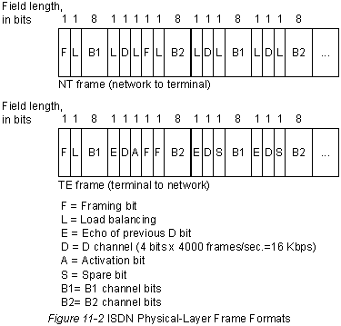
Physically to the same chain can be connected to many devices ISDN users. For this configuration, the collision can be the result of the simultaneous transmission of two terminals. Therefore, ISDN provides means for determining conflicts in the communication channel. When the device receives NT bit D from THOSE it this bit reflects the echo signal back into the next position E-bits. THOSE expects neighboring E bit must be the same as that of the bit D, which he gave in the past.
Terminals cannot transmit in the D-channel as long as they do not recognize the specific number of units (indicate "no signal"), corresponding to a predetermined priority. If the device detects any bit in the channel with the echo signal (E), different from his bits D, it must immediately cease transmission. This simple method guarantees that only one terminal can transmit its D-message. After successful transfer, the D-message priority of the terminal becomes lower, provided through pre phenomena of the claim to transmission to detect a greater number of consecutive units. Priority in terminals may not be increased until such time as all the other devices on this the line will not have the opportunity to send D message. Telephone communications are more higher priority than all other services, and information exchange signals has higher priority than designalicious information. Level 2
Level 2 of the Protocol of exchange of signals ISDN Link is Access Procedure, D channel (Procedure access the communication channel, D-channel), also known as LAРD. The LAPD is similar to the "Management data channel high level (HDLC) and the Procedure of access to the communication channel, balanced" (LAPB) (see Chapter 12 "SDLC and its derivatives" and Chapter 13 "X 25", which provides more detailed information about these protocols). As can be seen from disclosing its acronym, LAPD is used in the D-channel in order to provide the flow and the corresponding the reception of the control and signaling information. The format of the data block LAPD (see Fig. 11-3) is very similar to the HDLC format; also, as НDLC, LAPD uses the block data supervisor, and information and unnumbered blocks of data. The Protocol The LAPD is formally defined in CCITT Q. 920 and SSITT Q. 921.
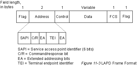
Field "flag" (flag) and "control" (control) LAPD identical to those fields in HDLC. The length of the field "address" LAPD can be one or two bytes. If the first byte is specified bits of the extended address (EA), the address consists of one byte; if not specified, the address consists of two bytes. The first byte of the address field contains a service access point identifier (SAPI) (the identifier of the access point to services), which identifies the the main entrance in which the services are provided to the LAPD Level 3. Bit C/R indicates if a block of data, a command or a response signal. Field ID the endpoint of the terminal (terminal end-point identifier (TEI) indicates whether the terminal is a single or a lot of them. This ID is the only of the above, which points to the broadcasting. Level 3.
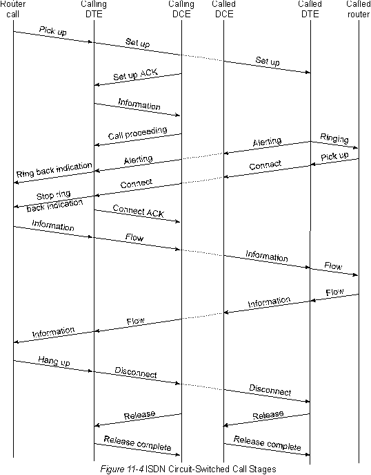
For signal transmission ISDN uses two specifications Level 3: CCITT 1.450 (also known as CCITT Q. 930) and CCITT 1.451 (also known as SSITT Q. 931). Together both of these protocols provide connections user-user, connections, circuit-switched and circuit-switched packages. They identify a variety of messages for the organization and completion treatment, information and mixed messages, including SETUP, CONNECT, RELEASE (DISCONNECTION), USER INFORMATION (INFORMATION USER), CANCEL, STATUS, and DISCONNECT. These messages are functionally similar to the messages that provides the Protocol H. 25 (for more details, see Chapter 13 "X 25"). In Fig.11-4 taken from the specification of the CCITT 1.451, shows the typical stages of treatment switching ISDN channels.
Publication: www.cxem.net