Now with the introduction of modern digital PBX service definition caller CUP is becoming more accessible. Most the prevalence receives service CUP in standard FSK (frequency modulation), allowing you to transfer the subscriber to not only the number of the caller, but also other information. Here in a concise manner will be described in an extended version of this standard Multiple Data Message Format (MDMF). More information get in the documents ETS300659-1 and ETS300659-2 European Institute for standardization in the field of telecommunications (ETSI).
In standard FSK data is transmitted at a speed of 1200 bit/s. Logical unit (MARK) is encoded by the frequency of 1300 Hz, a logical zero (SPACE) - 2100 Hz. Information is transmitted byte by byte, each byte begins with a start bit and SPACE ends with a stop bit MARK. Up to ten of stop bits can be added between bytes. Generalized timing diagram of the transmission shown in Fig. 1.

Information is transmitted between the first and second ringing signals, the duration pause T1 is 500...2000 MS, pause time T2 is not less than 200 MS. The message is preceded by a signal CHANNEL SEIZURE (seizure channel), representing a sequence of 300 interleaved bits are 0, 1,...0, 1 or 30 bytes 55N. The duration of this signal is 250 MS. Then, the signal MARK SIGNAL consisting of a logical block units with a duration of 180 ±25 MS or 80 ±25 MS operator selectable. This is followed directly by the message. A message is a set of parameters. Each parameter consists of three fields. The first field is the type of the parameter is one byte in the HEX format, which specifies the Caller ID device how to interpret the following two fields. Second field - parameter length (byte), is the number of bytes of data stored in the third field. The third field is the parameter data is ASCII codes in accordance with the CCITT recommendations, the most significant bit is always 0.
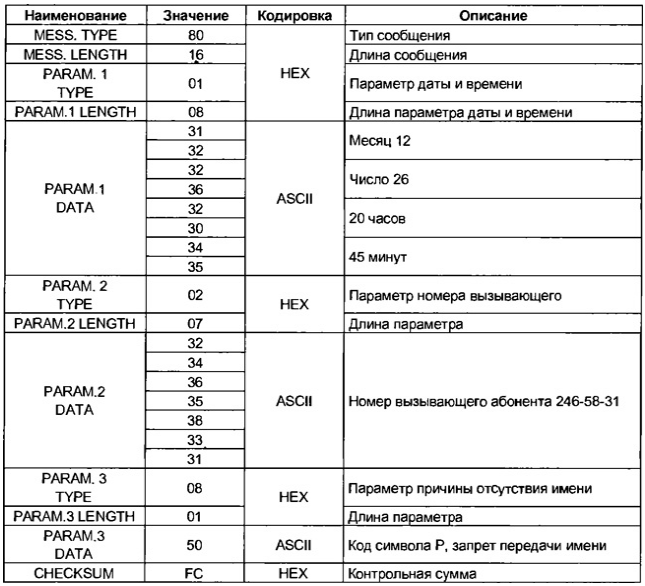
A typical message format shown in Fig. 2.

MESSAGE TYPE (message type) - for advanced format equal N.
MESSAGE LENGTH (message length) - number of bytes in the message, excluding the bytes MESSAGE TYPE, MESSAGE LENGTH and CHECKSUM, expressed in a single byte.
PARAM. 1 TYPE - setting the date and time equal to 01N.
PARAM. 1 LENGTH - the byte length of this parameter is always equal N.
PARAM. 1 DATA - information about the date and time of the incoming call is passed to the following sequence: bytes dozen months or About 1, byte units months from 0 to 9 bytes of tens of days from 0 to 3, byte units days 0 to 9, bytes tens of hours from 0 to 2, byte units hours from O to 9, bytes tens of minutes from 0 to 5, byte units of minutes from 0 to 9. This parameter is optional and may not be transmitted.
PARAM. 2 TYPE - parameter caller equal 02N, if the number is transmitted.
PARAM. 2 LENGTH - the byte length of this parameter.
PARAM. 2 DATA - the actual number of the caller is transmitted in ASCII code, starting with the most significant digits, the maximum length is 20 bytes. This parameter is mandatory and always passed. However, if the caller is included CLIR, PARAM. 2 TYPE is N, PARAM. 2 equal LENGTH and 01N PARAM. 2 DATA equal to the ASCII code of "P" ("Private"). If the station the caller does not support the transmission Protocol CLIP, then PARAM. 2 TYPE equal N, PARAM. 2 equal LENGTH 01N and PARAM. 2 DATA equal to the ASCII code for "On".
PARAM. 3 TYPE - parameter name caller equal NEH, if the name is transmitted.
PARAM. 3 LENGTH - the byte length of this parameter.
PARAM. 3 DATA - the name of the caller is transmitted in ASCII code, the maximum length of 50 bytes. This parameter is optional and may not be transmitted. If the PBX sends this option, but the caller blocked the transmission of his name, PARAM. 3 TYPE is N, PARAM. 3 LENGTH equal 01N and PARAM. 3 DATA equal to the ASCII code of "R". Also PARAM. 3 DATA is equal to ASCII code "O" in the case. if caller name is not available for any other reason.
CHECKSUM - byte checksum, which is the binary addition modulo 256 the sum of all the bytes of the message, beginning with the MESSAGE TYPE, except byte CHECKSUM. This Protocol does not provide error correction, and, if the checksum is not zero, the message is discarded.
A list of passed parameters is determined for each PBX. Standard provided backup codes settings to use a specific telephone operator. The parameters can be passed in any order. For compatibility unknown parameters are discarded by the Caller device ID. If both parameters are present, it is used only the first.
Simple format SDMF (Single Data Message Format) is a special case of advanced format and is currently rarely used. In this format transmitted only two options - date / time, and subscriber number. The message type equal NEH.
In table byte-an example of transmission of rooms 246-58-31 20 hours, 45 minutes, December 26, indicating the reason for absence of caller name.

Invite readers to repeat own design consoles Caller ID, which is compatible with SOME and MDMF format. Performance design tested on a real phone lines. The device is connected in parallel telephone to the phone line with a linear voltage battery 60 48... V. It is characterized by ease of management, reliability of identification, extremely low power consumption from the power source and from the telephone line. The prefix does not interfere with faxes, answering machines and other devices in automatic mode, and meets the requirements of standards for connecting subscriber devices. Structurally, can be performed in a separate housing or is built into the phone.
The device is powered by battery of three cells AA or AAA battery or from the battery voltage 4...5 V. Provides trickle charging of batteries, a small current from the line. Current consumption from the telephone line when stowed the phone in standby mode (when IPIT = 4.5 In) - not more than 0.1 mA, and the current charging power source is not less than 0.01 mA. The average current consumption from the power source in other modes - not more than 1 mA.
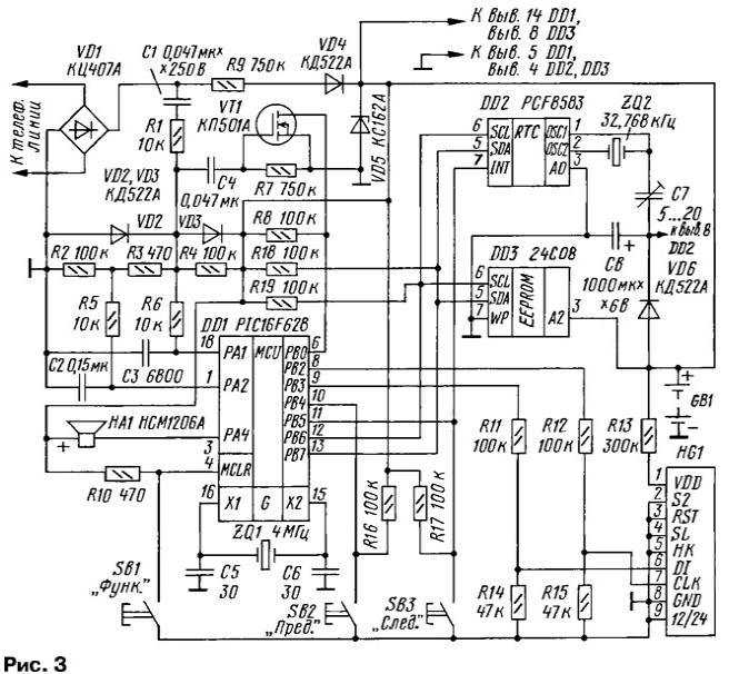
Diagram of the device shown in Fig. 3.

Memory consoles - sixty-three incoming number. The memory is organized on the principle of "first in - first out". Two buttons SB2 ("PREV") and SB3 ("Next") you can "scroll" the memory in the direction earlier calls and towards late calls. In memory are written to the room, the time and date of call. Provides economical use of memory, i.e. if the same subscriber dials to you at intervals of less than 10 min, it the number is stored in memory once and fixed the time of the last call. When the power off information in memory and work hours saved at least 3 min (depends on the capacity of the capacitor C8), which is sufficient to replace elements power. The number of new calls that are recorded in the memory after the last viewing it, is displayed on the indicator. Counter new calls is reset after watching memory.
Management of the device is performed through a menu of three functions: setting alarm clock, clock setting and clear the memory. The menu functions by pressing button SB1 ("Funk.").
The heart of this device is a microcontroller PIC16F628 (DD1). Decoding FSK through software. Use one of the built-in Comparators, conclusions RA1 and R are its inputs. The reference voltage circuit is formed R2R3R4, resistor R3 sets the offset between the inputs of the comparator 10...15 mV.
Cascade transistor VT1 is the simplest comparator for analyzing call of the signal. Conclusion PB0 controller DD1 configured as an external source of interrupts on the front. Chain R9VD4 while connected to a telephone line provides recharging GB1 current in the range 10...20 mA. The Zener diode VD5 protects the power circuit from possible surges. It is desirable to use import Zener with good toughness characteristics, depends on total consumption.
For sound button presses serves as a sound emitter with HA1 built-in oscillator on the operating voltage of 6 or 12 V. If you do not want the sound emitter 1 can be omitted. Chip DD2 in this design only used as a clock, timer, calendar and alarm clock.
To store the defined number uses flash memory S (DD3). For each room is 16 bytes. Information is recorded in binary-coded decimal format, ie 4 bytes reserved for the date and time of the call, and 12 bytes for rooms with a maximum length of up to 24 digits. Chip DD2 and DD3 interface l2C is connected to the controller DD1.
At power-up initialize the registers of the controller DD1 hours and DD2. The timer chip DD2 interval is set to 7 C. the device enters standby mode, the controller executes the SLEEP instruction. It can be activated by one of the following events: on the front entrance RVO (incoming call), changing the status of the inputs RV4, RV (pressing buttons or pulse at pin INT DD2), clicking the button SB1 (reset controller). The program analyzes the reset type, and if it's a "hot" restart (button SB1), then the menu functions.
With a period of 7 on the INT pin of the chip DD2 pulse appears on which the controller reads the registers, minutes and hours from the chip DD2 and loads these the values of the indicator HG1. This prevents automatic switching the indicator in the stopwatch mode. In sleep mode, the ratio of active time the controller to the time spent in SLEEP is 1:7.
When an incoming call to the first call, the PBX signal activates the DDI controller, the FSK message is decoded and written to the buffer. The adopted code is parsed displayed on the display and in the BCD format is stored in memory. After this, the controller enters standby mode.
In view incoming calls memory keystroke activates the controller, from memory selected information about the number, time and date of the call and displayed on the indicator. Two seconds is indicated by the number following two seconds is indicated date and time of the call.This cycle is repeated three times, then the device enters the standby mode. The mode of the incoming call has priority over mode view memory. The menu functions, i.e. the reset has the highest priority.
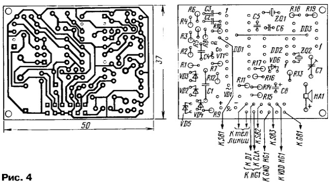
The device is assembled on a single-sided PCB (Fig. 4).

Before installation items you need to install a jumper, passing under the leads of the chips. Capacitor C1 should have a capacity in the range of from 0.022 to 0,047 µf and be designed for a working voltage of at least 250 V. the capacitance of the capacitor C3 can from 4700 to 10000 PF.
To establish the device requires basic multimeter (preferably digital), oscilloscope with an input impedance of 10 megohms and the battery elements or battery voltage 4.5...4.8 V to power the device. You will also need thin screwdriver with an insulated handle to adjust trimpot capacitor C7. With proper Assembly of the healthy components of the device starts working immediately and it is only necessary to check the operation of the comparator VT1 and current consumption.
YOU CANNOT CONNECT THE DEVICE TO A TELEPHONE LINE, NOT INCLUDING ПРЕLWАРИТЕЛЬНО FOOD!
Turning on the power of 4.5. .4,8 In using the meter and preset at the limit of measurement of not less than 5 mA DC. Approximately 5 the console will enter standby mode (the indicator will display the time and counter calls), the current consumption must not exceed 50 mA. If the current is more or consoles are placed in standby mode, it is necessary to check the quality installation, the firmware of the controller and the Zener diode VD5. In standby mode every 7 with the controller regenerates the indicator, so that milliammeter reading short-term increase.
Turning on the power directly (without meter), the plug conclusions diode bridge VD1 (for phone lines) to the line in the gap one of wires turn on the milliammeter. The prefix must be in standby mode, when the current in the circuit being measured must not exceed 100 mA.
Now you need to check the operation of the comparator VT1. Plug conclusions diode bridge VD1 directly to the telephone line. When an incoming call for the withdrawal of RVO the controller should be pulses, shape close to rectangular.
The last stage of building - adjust the accuracy of the clock capacitor C7. Do it in operation. If you watch "lost", slightly rotate the rotor C7. Repeat this operation until you get the exact clock rate. Use dielectric screwdriver, since the introduction of capacity in the circuit of the oscillator chip DD2 may cause a failure in his work.
Chips used are sensitive to static electricity, so use network-isolated "grounded soldering iron capacity of not more than 40 W. All operations on the installation complete when the power is off.
A few words about how to operate the console. Button SB2 "PREV." leafing through the memory in the direction of the earlier calls, and the button SB3 "Trace." - towards a more late. The console will show the number, date and time of the call, and then will automatically go into standby.
To enter the setup menu press and release the button SB1 "Funk.". To select functions use the SB3. To enter the function press SB2.
F1 - set the alarm. On the display from left to right will appear switch alarm ("- "alarm off "P" alarm on) and the values of hours and minutes. To select a value, use the button SB3, for change - SB2. To exit the function, press the button SB3 for a time not less than 0.5 with and release.
F2 - set the time and date. The indicator will appear from left to right values date, month, hours and minutes. To select a value, use the button SB3, for change - SB2. To exit the function, press the button SB3 and hold it less than 0.5 s, and the time signal release.
F3 - clear all memory numbers. Upon entering this function, you have 10 to transaction confirmation button SB2. Output - automatically.
No other setting is required.
A program code of the controller fsk6.zip. The configuration word is contained in the HEX file.
Author: V. Bakul, Chisinau


