


")

Phones with automatic call identification (caller ID) are popular from the moment of their appearance. Recently in connection with the installation of modern equipment on the old PBX caller ID no longer work. In this article, the author talks about the version of the device identification service, working with the service CLIP (Calling Line Identification Presentation, which literally means "caller identification") on the digital stations.
We have been using the opportunity to identify subscribers thanks the radio Amateur-enthusiast, who first hit upon the idea to assemble the device, capable to get from the PBX subscriber number. All this worked fine on the old Soviet PBX, but with the commissioning of a modern telephone exchanges foreign manufacturers good old caller ID turned into a jukebox - the music is playing, alarms are ringing, a pleasant female voice talking, but not doing his main function - identification number. This was expected because in Soviet ATS were not presumed to provide the service to the subscriber - the caller ID equipment primarily intended for automatic billing long distance calls. Our caller ID simply "cheated" ATS, and she, "thinking", the room requires her long-distance station, was given a number to the subscriber. But with foreign stations, this focus does not, the opportunity to block the issuance of caller ID.
But not worth much upset, because the old way of determining the number has the disadvantages. There is just a number no longer than seven digits and category the subscriber. For determining the number must be a connection between the subscriber and PBX that when you go rates brings inconvenience to the caller. Each of us have experienced a situation when you dial a number on the the end triggered the caller ID and no one to talk to. This is especially unpleasant when long-distance calls, where the rates are especially high.
Now subscribers of digital stations can order the service definition room (CLIP), and other services for money. But now it is guaranteed service, pay your money - you get the service. Service CLIP free from the above described disadvantages and has more opportunities. Naturally, to use this service, it is necessary, first, to order it from their telephone operator in the same way as other services. Secondly, you must have caller ID (generally called Caller ID) compatible standard equipment your telephone operator.
Since the early 90-ies of the last century, manufacturers of telecommunications equipment provided for the possibility of issuing caller as one of the digital stations. At the same time developed two standards.
Standard DTMF (Dual Top Multi-Frequency (frequency encoding) for the first time was proposed by engineers at Bell Labs for data transmission via radio channels, and then began to be used in other transmission systems Here each transmitted symbol is represented by a sum of two different frequencies of the eight possible. All at our disposal sixteen characters: ten digital 0 to 9 and six service- "*'*, "#", "A", "b", "C", "D". The layout of frequencies shown in the table.
Combining these symbols, we get the desired message. The benefits of this standard are reliability and prevalence of DTMF and the simplicity of the equipment identification service. In relation to service this CUP the standard was developed in several stages, so not all stations support it to the full extent.
The first stage involved the transfer of only caller or last pereadresuem. In this case, it is impossible to determine whether forwarded call. Transmission format: D S1 S2 S3 …Sn S.
The second phase was passed only the caller's number or last pereadresatsii, but in this case it is possible to determine what number received: the number of the caller or pereadresuem subscriber. Transmission format of caller: A S1 S2 S3 …Sn S. transmission Format of pereadresuem the subscriber-DS1 S2 S3…SnC.
The third phase was transferred and the number of the caller, and the number of the last pereadresuem: (A S1 S2 S3…Sn) (DS1 S2S3…Sn)C.
In the latter stages of the Protocol was expanded to provide additional parameters. Have the opportunity to include in the message to five pereadresuem rooms and additional information codes that indicate how to interpret the message. Transmission format: (A S1 S2S3…Sn)(DS1 S2 S3…Sn)......(D S1 S2 S3…Sn) (B S1 S2) C.
The symbols A and D are starting calling and pereadresuem subscribers, respectively, In the starting symbol for passing parameters, Sn - the number, n is an integer from 1 to 15. Information transfer is always ends with the character C. the duration of the tone of each character and the pause between them 70 MS.
At any of these stages provides for the transfer of information about the impossibility providing a calling, for example, if the protected room service (CLIR). In this case is transmitted sequence (1 0). The number of digits in the transmitted rooms may not be more than fifteen. The first two digits is the zone number. For to the called subscriber has received the calling, it is necessary that the signal the system of the whole chain of stations was supported by the required data transmission Protocol. Use DTMF for determining the number has spread mainly in European countries.
On the American continent and in Asia are mostly standard FSK (Frequency Shift Keying - frequency shift keying). In my opinion, this standard more researched, compared with DTMF, at least at this stage. Originally this method was developed for data transmission over telephone networks between the modems. Here, the bit "0" is encoded by the frequency of 2100 Hz and the bit "1" is a frequency of 1300 Hz, the transmission speed is 1200 bit/s. Bits going into bytes with length eight bits and bytes are combined into a message.
Thus, in our disposal there are 256 characters. The opportunity arose to convey not only the numbers but also the symbols of the alphabet. Now is huge number Caller ID standard FSK, allowing to provide the customer not only number, time and date of the call of the caller, but also his name. As for name calling, the possibility of its transmission depends primarily on the telephone service provider, the remaining parameters are passed for sure.
Telephone station before issuing numbers must somehow inform a subscriber terminal about their "intentions". Here, too, there are several options: change the polarity of the telephone line, off line voltage on normalized time interval or decrease in line voltage to a certain level. The message can be transmitted to the first ringing signal or between the first and second.
In this article we will consider the design of Caller ID DTMF. Device works like a console, connected in parallel to any telephone on analog telephone line voltage linear battery 54…60 V. Console very easy to manage, reliable identification service, the maximum low power consumption from the power source and from the telephone line. Console interfere with the use of faxes, answering machines and other devices operating in automatic mode and meets the requirements of standards for connecting subscriber devices. Structurally, it can be performed in a separate the housing or integrated in the phone.
The power of the game device is a battery of three cells or batteries AA or AAA. Provides trickle charging of batteries a small current from the telephone line. Current consumption from the telephone line when laid the handset is in standby mode (when u pit = 4.5 V) - not more than 0.1 mA, and the current recharging the power source is not less than 0.01 mA. The current consumption from the source meals: at the time of recruitment or location - less than 5 mA, when it is removed the tube or viewing the memory is not more than 0.3 mA.
Memory consoles - twenty-six numbers, organized on the principle of a first - in-first-out. Two buttons can be "flipping" the memory in the direction earlier calls and towards late calls. In memory of the recorded area, number, time and date of call. Provides economical use of memory, E. if the same caller calls to you at intervals of less than 10 minutes, its number is written into memory once and fixed the time of the last call. With the power off information in memory and work hours saved not less than 3 min, which is sufficient to replace the batteries. The number of new calls recorded in the memory after the last view is displayed on the indicator. Counter new calls is reset after watching the memory.
If your phone works in the tone mode, the dialed number duplicated on the display, so you can control the accuracy set.
Diagram of the console shown in Fig. 1. The device is assembled on three chips. In the quality indicator used LCD from China phones PANAPHONE or similar. This 10-digit LCD meter with built-in controller Holtek. The main element of the design is the microcontroller PIC16F84A (DD2). To decode the DTMF tones used chip The DTMF decoder (DD1) inclusion in the model. Hardware decoding provides higher noise immunity and reliability, unlike software deciphering. In addition, simplified and minimized the program.
(click to enlarge)
Chip DD3 combines clock, timer, calendar, and static RAM, which preserves the defined number. The l2C interface is emulated by software the findings RV and RV7 controller DD2. The larger the capacitance of the capacitor C7, the longer stored memory numbers and the clock when the power is off. Trimmer capacitor C6 are required to install the accuracy of the clock.
Cascade transistor VT1 is the simplest comparator to analyze the state the telephone line. The RB0 output controller DD2 configured as an external source of interrupts on the front. The Zener diode VD4 serves to protect the entrance from possible overvoltage. When free line, the transistor VT1 is open and in reducing the voltage on the telephone line is below 50 it closes In. To set this cascade should be treated very carefully about what will be discussed further. If your PBX indicates the transmission of a room by changing the polarity of the line, then this node will require refinement, as it is necessary to form the front when changing polarity.
For sound button presses and determining the number of sound the emitter HA1 with a built-in oscillator on the operating voltage of 6 or 12 V. In the mode of determining the number of the binary code of each decoded symbol DTMF appears on the findings of the D1-D4 circuits DD1 and accompanied by a high level on the output DSO same chip, which opens the transistor VT2, which includes the audio signal and provides a low logic level on pin RA4 controller DD2.
Mode identification service this pin configured as an input and Gating code on the inputs RA0 - RA3 of the controller. In the absence of a DTMF signal on the input of the decoder DD1 at its output DSO there is a low level, the transistor VT2 closed, and the entrance RA4 controller DD2 through the internal circuit of the emitter HA1 connected to the supply circuit. In other modes, the decoder DD1 is off, the output RA4 configured as open-drain output that controls the power HA1.
While on-hook elements R10, VD5 provide flowing in the supply circuit current, sufficient to compensate the current consumption in standby mode and charging batteries. The Zener diode VD6 serves to protect the circuit from possible over voltage. It is desirable to use a Zener diode with a sharp drop characteristics, depends on the total consumption.
To display supply voltage of 1.2 1.7 In…serves as a resistor R19. Under Bira its in a small range, you can control the contrast indicator Download the indicator is produced from outputs of RB2 and RB3. Voltage dividers R13R14 and R15R18 are used to align the signal levels between the outputs RB2 and RB3 (DD2) and inputs DI and CLK indicator.
At power-up initialize the registers of the controller DD2 hours and DD3. The power of the chip DD1 turned off due to low level at the output RB1 DD2, timer DD3 is configured as an interval of 7 C. After that, the device enters standby mode, the controller executes the command SLEER It can be activated one of the following events: front input RB0 (incoming or outgoing call), changing the status of the inputs RB4, RB5 (pressing buttons or pulse at pin INT DD3).
Every 7 on the INT pin of the chip DD3 pulse appears on which the controller reads the registers, minutes and hours from the IC DD3 and loads these the values of the indicator HG1. This prevents automatic switching the indicator in the stopwatch mode. In sleep mode, the time activity the controller to the time spent in SLEEP is 1:7.
For an incoming call before issuing the first call signal the PBX takes the line and reduces the voltage to 43…45 V. the Transistor VT1 is closed, the controller DD2 activated, turns the power circuits DD1 and samples the outputs of the decoder D1 - D3 and DSO. The adopted code is recorded in the buffer memory, parsed, and if the first character is A or D, a decision is made that the incoming call transfer rooms. Information about the number, time and date of the call is packaged, is recorded in the memory and displayed on the display. Upon receipt of the stop symbol With the power the DD1 chip off.
If the first character is different from the above, it is believed that this outgoing call. In this case, each adopted code extends the time of power on DD1 another 7 C. Thus, when an outgoing call key codes in parallel the connected device is displayed on the indicator. Naturally, the device should to work in the tone (i.e. DTMF) mode.
In view incoming calls memory keystroke activates the controller, from memory selected information about the number, time and date of the call, unpacked and displayed on the display. Two seconds is indicated by the number following two seconds indicated date and time of the call. This cycle is repeated three times, then the device enters standby mode. Modes of incoming and outgoing calls have priority over view of memory.
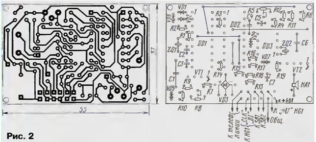
The device is assembled on a printed circuit Board (Fig. 2). Before installing the components you need to unsolder the six jumpers. Resistors, diodes and bridge VD3 set vertically. The distance between the centers of the holes for the resistors and diodes to 2.5 mm Bridge VD3 can be replaced by imported RB157, and the transistors QP - on KR1014KT1. You can use SMD components that contact raspalaut site. The DD1 chip can be replaced by CT, CT, CT, CT (first letter may be different) or domestic CRUZ.
To establish the device requires basic multimeter (preferably digital), oscilloscope with an input impedance of 10 megohms, adjustable DC voltages up to 60 V, which we will replace telephone line and the battery elements or battery voltage 4.5…4.8 V to power the device. Also you will need a thin Screwdriver with an insulated handle to adjust trimpot the resistors.
With proper Assembly of serviceable components, the device begins to work immediately, and needs only to set the clock frequency controller resistor DD2 R5, configure comparator input resistor R8 and to check current consumption. Before establishing need to install the sliders adjusted resistors in average position.
You CANNOT connect the device to a telephone line, not pre-setting the batteries!
Turning on the power 4,5 4,8…In through the milliammeter mounted on the limit measure 5 mA DC. Approximately 5 console will enter standby mode (the indicator will display the time and counter calls), the current consumption during this should not exceed 30 mA. If the current is more or console does not enter standby mode, you must check the Zener diode VD6, quality of installation and firmware of the controller. In standby mode every 7 to the controller regenerates the indicator, therefore, the current is temporarily increased to 100 μa.
Turning on the power directly (without meter). The output controller 15 DD2 plug the probe of the oscilloscope and hold one of the buttons, set the period pulses of 15 μs trimming resistor R5. Release the button. Clock frequency not critical and can be set with an accuracy determined by the scan oscilloscope
Without disconnecting the power plug conclusions diode bridge VD3 (for telephone line) to a regulated source 60 and the probe of the oscilloscope to the output 6 controller DD2. At a voltage of 50 To set a trimming resistor R8 the voltage level at pin 6 is not more than 0.3 V. Reduce the voltage up to 46 V, when this is the level at pin 6 should not be less than 3 V. Otherwise you need to check the Zener diode VD4 and the transistor VT1.
Set the voltage 60 V, and the gap of one of the wires included milliammeter. The prefix must be in standby mode, the current in the circuit being measured must not exceed 100 mA.
Now the console can be connected to a real phone line and test decoder DD1. Lift the handset of telephone device that is included in tonal mode. The display will be cleared, you have 7 to time to gain arbitrary a sequence of numbers. They should appear on the display, and each press be accompanied by an audible signal.
If no display, it is necessary to check the correctness of the installation, the correctness of the decoder and the quartz resonator ZQ1 . Remember that the power of the decoder stays on no more than 7 seconds after the last received DTMF signal. You may not will show some figures. This usually occurs with telephones Chinese production and other devices, much loading the telephone line. In this case, measure the voltage in a telephone the line at the removed tube. If it is less than 8 In, turn on consistently with the findings telephone resistors of 100 Ohms and a power of not less than 0.5 watts. On the connection quality is not affected, but will help get rid of the problem.
Proper configuration of the comparator and display numbers when dialing from parallel apparatus guarantee identification for an incoming call.
The last stage of building - adjust the accuracy of the clock trimmer the capacitor C6. Do it in operation. If you watch "leave", slightly rotate the rotor C6. Repeat this operation until you get the exact clock rate. Apply dielectric screwdriver, since the introduction of capacity in the chain oscillator chip DD3 may cause a failure in his work.
Chips used are sensitive to static electricity, so use network-isolated "grounded soldering iron capacity of not more than 40 W. All operations on the installation complete when the power is off.
A few words about how to operate the console. It is very simple. Button SB1 "PREV" leafing through the memory in the direction of the earlier calls, and the button SB2 "NEXT" - in towards the later. To enter playback mode memory must first click to be not less than 0.5 s. the Console will show the number, date and time of the call, and then will automatically go into standby.
To enter the clock setting mode, press both buttons simultaneously for a time less than 0.5 s. the indicator will appear from left to right the values for the date, month, hours and minutes. To select a value, use the button SB2, and to install SB1. For exit the installation, click SB2 and hold not less than 0.5, and at a signal the exact time - release.
No other setting is required
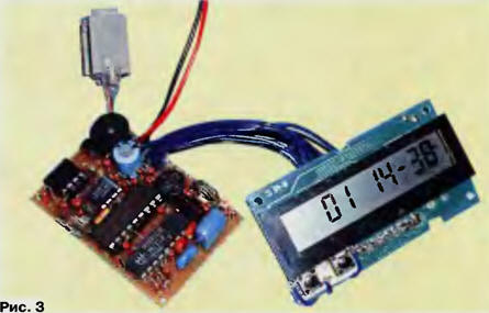
In Fig. 3 shows the device in assembled form.
A program code of the controller.
The programming mode is turned off watchdog timer WDT enabled PWRT timer and oscillator circuit RC.
Author: V. Bakul, Chisinau, Moldova