


")

The device is intended for use on the telephone line is connected with two parallel and allows you to have the indication, that removed another tube, except the one from which you speak.
The principle of operation of this scheme is based on the use changing the voltage on the telephone line when it is removed the tube on two parallel SHE at the same time. If answered in only one TA, the scheme works as described above, - led lights HL1, and the transistors VT1 and VT2 may be absent (Fig. 2.4). When removing tube one THE line voltage will change by about 1…5 V ( depends on the internal resistance of installed telephones).
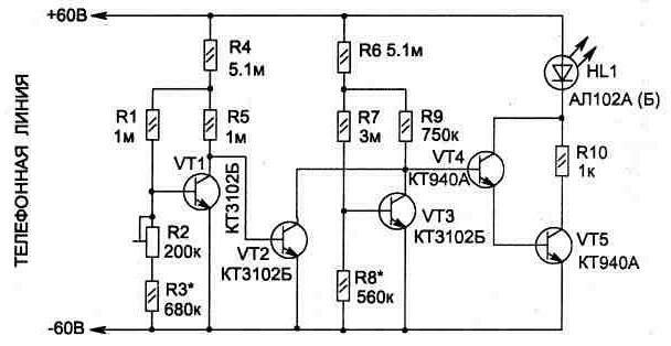
Fig. 2.4
Transistor VT1 is the analyzer voltage level in the line, and its mode is set by the resistor R2 (coarse adjustment is made the resistor R3) so that when the voltage in line 0.5 In he mode saturation moved into the locked state, which should lead to saturation of the transistor VT2 and the cessation of illumination of the led. It will be the indicator of you may tapped on THE parallel. In normal condition when removed one tube should be on HL1.
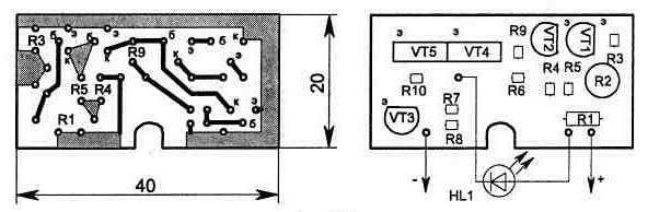
Fig. 2.5
A printed circuit Board, and the elements in it is shown in Fig. 2.5. The design of the Board is designed to fit in standard phone Jack (see shown in Fig. 2.3 the case). Resistor R2 compact, type SDR-19a.
The device is pre-configured by the method for the circuit in Fig. 2.1, is connected to the line, observing polarity, and the final the setting is performed on TL resistor R2 when taken off immediately two phone of the tube. When this led HL1 shall extinguish.
Publication: www.cxem.net