In multi-functional telephone apparatus with a rated current consumption 60...200 mA (power supply circuit 5 In) are most commonly used linear regulators the voltage on the chip CREE or its equivalents. It happens that the heat sink stabilizer calculated by the "lower limit", and the chip is strongly heated. For improvement of the thermal regime and improve the reliability propose to replace linear the stabilizer is simple to assemble and configure pulse, performed on a specialized chip MSSA f. Motorola.
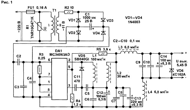
Diagram of the upgraded network adapter installed in it pulse the voltage regulator shown in Fig.1.

The chip is available in MSA two versions: in the case DIP-8 (with index P) and in a small package SO-8 (with index (D). The chip keeps working when the input voltage is 3...40 In and allows you to create step-up step-down and inverting voltage converters [1].
In this case, the chip is included as a buck Converter. Its use in this mode is rational in that case, if the input the stabilized voltage exceeds the output is more than 2 times. With less the difference of input and output voltages the efficiency of the stabilizer is reduced, approaching the efficiency linear. The minimum difference between the input and output the voltage required for normal operation of the down Converter, - 3 V.
The mains voltage (220 V) via the fuse FU1 is supplied to the primary the winding step-down transformer T1. The transformer used by the adapter from the telephone set and the fuse when it is introduced the revision. Unfortunately, most manufacturers of network adapters hard not I wish to install in your products fuses, thereby putting under threat safety equipment and dwellings. Varistor R1 protects the network from transformer breakdown of insulation of the wires of the primary winding by surges in the line voltage.
The voltage from the secondary winding of the transformer through the safety resistor R2 is supplied to the bridge rectifier diodes VD1...VD4. The Capacitor C1 smoothes the rectified voltage ripple. Resistor R3 is required to protect circuits DA1 overload. The oscillator frequency chip set capacitor C11. A diode of a Schottky VD5 and the inductor L1 are involved in the transformation high input voltage to low output is stable, the value of which depends on the resistances R4 and R5. Since the comparator chips strives to maintain at pin 5 DA1 voltage of approximately 1.25 V, the more the resistance R5, the higher the output voltage. Inductors L2, L4...included LC-filters. smoothing of the output voltage ripple. The Zener diode VD6 protects the load from damage in case of malfunction of the regulator (in this case burns protective resistor R2).
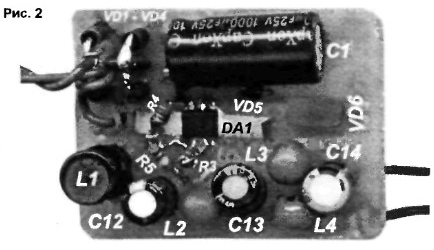
Details and design. Most of the parts mounted on a circuit Board size 44x32 mm (Fig.2).

The findings of the parts are connected by conductive vias. The transformer T1 will fit any with an overall capacity of not less than 4 watts and the voltage on the secondary winding 10...17 V. the higher voltage at the output rectifier, consumes less current stabilizer, constant voltage load. Varistor R1 can be any of the series TNR, FNR rated voltage 430 (470) In, for example, FNR-C. The resistor R2 is applied in SMD-performance. On CSOs place you can use resetable fuse rated current 0.2 A [2] or similar fusible.
Resistor R3 - homemade wire, made of thin enameled wire with high resistance wound on a low-power resistor. The remaining resistors - small, any type. Oxide capacitors - import analogues C50-35, nonpolar - ceramic, SMD-performance. In place of the diode VD5, you can apply any low-power diode of a Schottky, for example, 1N5819. A Zener diode can CSA replace XV, 1N5341. Bridge rectifier generally suitable one. which installed in the adapter initially. You can gather it from the four series diodes 1N4000...1N4007. CD. CD, CD. Suitable low-power diodes the Schottky, when this efficiency of the stabilizer will increase slightly.
All chokes I used a small, industrial manufacturing, with the resistance of the windings is not more than 0.1 Ohm. On the efficiency of the stabilizer in the first they depend on the characteristics of the inductor L1, which may be the inductance 100...500 µh and more. To begin, I took the throttle, consisting of 35 turns winding wire 00.37 mm is wound on a ring of low frequency ferrite MN with an outside diameter of 16 mm, and then picked up the choke available ready (compact) with the H-shaped ferrite core (which the efficiency of the stabilizer is not deteriorated). To the chip MSA (MSA) to improve its reliability by using thermally conductive adhesive glued small U-shaped brass radiator plate dimensions 30x4x0,3 mm.
My stabilizer is configured to output voltage 5.45 In taking into account the losses in connecting cord (0.05), as supplied from the upgraded adapter the phone has a node recharge the backup power source and modified for this reason, the power circuit of the CPU Board. If you want the output voltage is 5 V, the resistance R5 is necessary to reduce to 3.6 ohms.
Before the upgrade the network adapter is the voltage regulator on a chip CREA when the load is connected consumed from the secondary winding transformer current of about 110 mA. and when you replace it pulsed supply current decreased to 70 mA. At the same time significantly decreased heating of the body of the adapter. The amplitude of the ripple voltage at the output of the regulator when the load current 100 mA does not exceed 40 mV at a frequency of operation of the Converter.
Literature
Author: A. Butov, S. CORBA the Yaroslavl region.


