


")

The disadvantage of a powered external microphone on the three wires can be eliminated. Below is a diagram with two-wire connection line, with better output characteristics than described above. Based on the scheme provided in the device remote microphone with amplifier (see figure 25). As a pre-amplifier uses a differential operational amplifier. Schematic diagram of the device shown in figure 34. 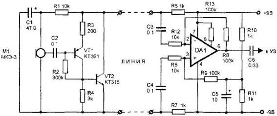
Figure 34. External microphone on the operational amplifier.
Work external microphone (left part of the diagram) described in detail in the description of the operation of the circuit Remote microphone with amplifier (see figure 25). Will focus on the description of the right side of the diagram. The basis of the right part of the diagram represents the operational amplifier DA1 type CRUD connected in the circuit of the differential amplifier. It is a low-noise operational amplifier with low current consumption. The scheme has a common mode rejection ratio input voltage of about 100 dB. This property is used to suppress noise induced in the wires and having a common-mode in nature. Useful signal and disturbance are removed from the load resistors R6 and R7 and through the NW and capacitors C4 receives the inverting and non-inverting input circuits DA1, respectively. As a consequence, the interference signal is attenuated in the chip 100 dB. Useful sound signal amplified by the operational amplifier 10. The signal gain can be changed by changing the resistance of resistors R8 and R9. The increase of their nominal values leads to an increase of the gain, defined as the ratio of R8/ R4, R9 R5). The signal amplified chip, with 6 output through the capacitor C6 is supplied to the main USC or tape recorder.
Resistors R10, R11 and a capacitor C5 create an artificial high point at which the voltage equal to the voltage of the power supply. This is because the power the device uses a single supply, and for normal operation of the operational amplifier bipolar need food. Resistor R13 sets the required current consumption of the chip.
Chip DA1 can be replaced by CRUD. But it is possible to use any other of the operational amplifier included in the model scheme with their correction circuits. Resistor R13 in this case is excluded from the scheme.
With proper details, the device starts to work without any further adjustment. Increase (decrease) the gain is possible by selection of resistances R8 and R9.
If the left part of the scheme to replace the scheme shown in Fig. 35, and from the right side to remove the resistors R6 and R7, it is possible to record on tape a phone conversation when removing the handset.
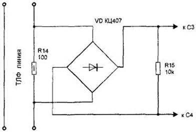
Figure. 35. A specialized microphone.