Amplifier, diagram of which is shown below designed to work in the frequency bands 1 - 5 and 6 - 12 the TV channels. The last amplifier stage is the emitter repeater, matching amplifier with a small wave the resistance of the cable (75 Ohm).

As work in УSW range repeaters tend to the self, in their input chain included Zapper resistance (R15), which can be calculated by the formula R = 2 p faLвх, where fa- limit frequency amplification transistor (transistors fa is usually in directories);
Lвх - inductance of the coil the input of the repeater. Winding these coils amplifier below. All coils wound on the frames with a diameter of 7.5 mm cores SSCR-1 round wire sew 0.15 mm.
Room coil L1L2
L3
L4
L5
L6
L7
L8
L9
L10
The number of turns2,5
3
2
2,5
2
2
2,5
2
2,5
2
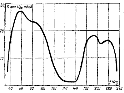
When establishing the amplifier should keep in mind the rotation of the core coils having on the scheme odd numbers will be to change the form the amplitude-frequency characteristics in the field frequency 175 - 230MHz, and the rotation cores coils with even accommodation form characteristics in the field frequencies of 50-100 MHz.
The amplifier is set at any УSW generator standard signals having the frequency range in which need amplifier to work. In as an indicator of output use a voltmeter with high impedance input, allowing to measure AC voltage frequency up to 250 MHz. Setting lead in the usual way, i.e. by changing the position of the cores coils, making to the shape of the amplitude-frequency characteristics of the amplifier perhaps less different from it is shown in Fig. 2.

Amplifier designed for connection to TVs sensitivity of 200-500 mV.
Author: V. Demyanov; Publication: www.cxem.net


