


")

When receiving television signals in the UHF range, many owners TVs are forced to use several different antennas that, at times, may to generate specific problems associated with the summation of the signals. To solve them help antenna amplifier provides amplification of signals, but also their filtering.
One of the problems with which the viewers have to deal with when browsing television programs - the need of receiving signals from different directions and with the different levels. This forces them to use two or more directed antenna, and at low signal level - active antenna [1, 2] or antenna amplifiers [3 - 5], we have to include the combiners or splitters television [6]. Unfortunately, this often does not provide the desired quality of reception. The reason for this doesn't necessarily lie in a poor feeder or failed it approval. For example, if you have several antennas, designed for work within the range, then the reception of the same signal, particularly powerful, will be possible by two or more antennas. However, in this case because different propagation time of the signal in the feeder appears multiplanimetric or a blurry image, even though the signal level is sufficient for high-quality reception.
This disadvantage can be eliminated by applying bandpass filters or selective amplifiers that emit one or more signals received from one antennas, and suppress interfering. And so - after each antenna, while filtering different channels. Then all the signals are summed. For range MB this is the challenge the use of amplifiers and filters considered in [7]. For the UHF range descriptions of such structures is almost there. So here are the options of selective amplifiers for the UHF range.
It should, however, note that the use of filters is not always it is advisable (though possible). The fact is that, firstly, the filters make attenuation, and when receiving weak signals that could affect the quality image. Secondly, the frequency response of filters, especially narrow-band, substantially depends from their alignment with the connection cables. Therefore, even small changes in resisting loads can greatly change the frequency response and reduce the quality of reception. To eliminate this undesirable effect, the inlet and outlet of the filter to install amplifier cascades.
A schematic diagram of a selective amplifier for the selection of one or more closely spaced signals shown in Fig. 1.
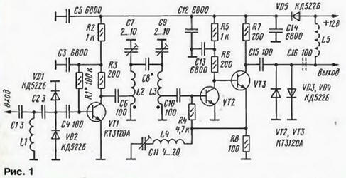
The device incorporates the bandpass filter of the two coupled circuits L2C7 and L3C9. Inlet filter installed amplifying cascade transistor VT1 and the output of the two stage the transistors VT2 and VT3. The total gain reaches 20…23 dB, and the bandwidth is determined by the bandpass filter.
Signals received by the antenna, enter the filter C1L1C2, which suppresses signals with a frequency of less than 450 MHz. Diodes VD1, VD2 protect the transistor VT1 from powerful signals and electrical interference from lightning. With input stage the signal passes in the first circuit L2C7. To obtain the necessary it quality factor, applied partial inclusion (to the tap of the coil L2). To contact circuit L3C9 switched capacitor C8 (capacitive coupling). The signal from the part turns coil L3 comes to the base of transistor VT2, and after amplification at base transistor VT3. The frequency response of the output amplifier to further enhance it selectivity can be adjusted by the adjustment circuit L4C11 in the chain return connection.
Diodes VD3, VD4 protect the amplifier from electrical discharges from the TV. They can occur due to the fact that the switching power supply modern devices using capacitors of small capacity connected to the network 220 V. Powered amplifier from a stabilized voltage source of 12 V and current consumption is about 25 mA. Diode VD5 will protect the amplifier when connecting to it power supply in reverse polarity. If it is to be nourished by a separate wire, the voltage is fed directly to the diode VD5, and if the lead-in cable is introduced into the amplifier decoupling elements L5, C16.
All the details of the amplifier are placed on one side of the PCB from bilateral foil fiberglass depicted in Fig. 2.
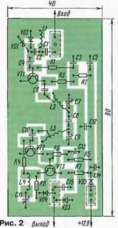
The second side of the Board left almost completely metallized. It only cut out areas for input, output and supply voltage (in the figure they are shown by the dashed line). Metallization of both sides connect with one another on the circuit Board soldered foil. After the configuration of the charge amplifier from parts close metal cap, solder it to her.
In the amplifier, you can apply the transistors CTA.B, but if you don't need high sensitivity, fit and CTA; diodes KDA, KDA.
Capacitors C7, C9, C11 - CH-25, other - K10-17, km, KLS; resistors - MLT, C2-10, C2-33, P1-4. Conclusions all of the items should be of a minimum length.
Coil L1 wound wire sew-2 0,4 mandrel with a diameter of 2.5 mm and contains 2,8 revolution. Coils L2, L3 made wire sew-2 0,7 mandrel with a diameter of 3 mm winding Length of 7 mm. They have three coil with a tap from the middle of the first revolution. Coil L4 is wound with the same wire and contains two turns, and the coil L5 - wire sew-2 0.4 and has 15 turns, both on the mandrel with a diameter of 4 mm.
The design of the capacitor C8 is shown in Fig. 3. It is made of two plates of tin or thick foil, which is soldered to the pads of the Board. By changing the distance between the plates, changing the capacitance of the capacitor.
The establishment of an amplifier begin with installation and inspection regimes necessary DC. The selection of resistor R1 achieve voltage 4-5 the collector of transistor VT1. Mode transistors VT2, VT3 is obtained automatically.
To adjust the frequency response of the amplifier using the panoramic indicator. Capacitors C7 and C9 adjust the contours of the desired frequency. At these values of the Central the filter frequency can be changed from 500 to 700 MHz. Bandwidth set by adjusting the capacitance of the capacitor C8. Thus in a small the range varies and the gain of the amplifier. Tuning capacitor C11 get maximum gain at the desired frequency.
The capacitance change of the capacitor C8 is possible to achieve the minimum bandwidth amplifier 10…12 MHz one-humped frequency response. It is necessary to define the signal only one television channel. If you need to select two adjacent channels, the bandwidth is increased to 40…50 MHz (bring plates of the capacitor S8) when the double-peaked frequency response with a slight irregularity. In addition, the frequency response of the filter also influenced by the location of the taps of the coils L2, L3.
However, the essential situation is complicated. For example, in Kursk in the UHF range the station broadcasts on the 31st and 33rd channels from one place and with a large capacity, and on the 26th and 38th channels - from another place and with less power. This option fairly typical of most cities in the country. Therefore, for the reception and allocation of signals the 31st and 33rd channels you can use the already-described amplifier. For receiving same signals 26 th and 38-th channel (or the other two with great frequency spacing) this amplifier is not suitable. Here is another that has two bandwidth, i.e., contains two filters.
Schematic diagram of the amplifier shown in Fig. 4.
The signal from the antenna through filter C1L1C2 is supplied to the first amplifying cascade transistor VT1. With it the output signal is divided, and two independent cascade transistors VT2 and VT3, each of them loaded on your bandpass filter: L2C10-С12L3 and L4C13-C15L5. To filters connected amplifying stages transistors V4 and VT5, the outputs of which are operating on the same load. The overall ratio the gain of this device is 18…20 dB, and the consumption current is about 40 mA.
In this amplifier used the same parts as in the above. Drawing his the PCB with the components represented in Fig. 5.
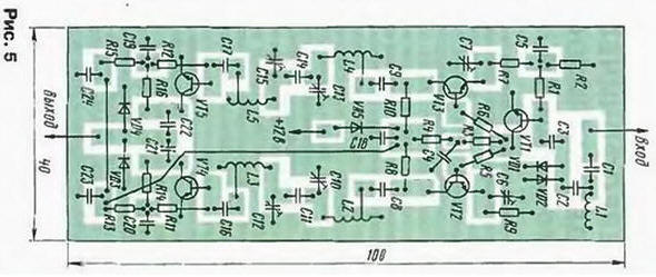
The establishment carried out analogously. The selection of resistors R11 and R12 set a constant voltage of about 5 V on the collectors of transistors VT4 and VT5. Filters tune in to desired frequency. Tuning capacitors C6 and C7 get maximum gain at selected frequencies.
If you need to narrow the bandwidth and increase the selectivity of the filter, achieve increasing the figure of merit contours, using a thicker silver plated wire in coils and rigged condensers with air a dielectric, or increase the number of contours.
Literature
Author: I. Nechaev, Kursk