


")

Offer antenna amplifier is designed to amplify signals and broadcasting television stations meter band.
- Stripe bandwidth, MHz, the signal weakening the edges of the range 3 dB..........50…350
- Level noise, dB..........3,5
- Input resistance in Ohms..........75
- Rated the load resistance. Om..........75
- The coefficient gain of voltage at the input signal 5 mV, dB, frequency MHz: 230..........41
Principal the antenna amplifier circuit shown in figure. It is collected in four the transistors included in the common-emitter circuit. A feature of the amplifier is the use of as a collector loads of transistors VT2-VT4 inductors that reduced blockage the amplitude-frequency characteristic (AFC) of the amplifier at the highest frequencies.
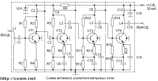
Zener diode VD1 type DA. Amplifier keeps working lowering the voltage power up to 4 V. In this case gain all frequency range reduced to 36 dB. For operation of the amplifier when low voltage Zener DO need replace XA or KS147A. Current, power consumption of power, will fall in this case up to 15 mA.
Amplifier mounted on four boards size h mm bilateral foil fiberglass thickness of 2 mm. One of the sides of the Board used as a screen. Board installed in a rectangular the recesses brass body and separated from each other baffle plate, soldered directly to foil surface boards.
Coils L1, L2, L4 contain 2.5, a L3 - 4 turns wire PEL of 1.0. The winding diameter coils L1-L3 - 12, a L4-Step of 20 mm. winding - 8 mm.
Establishing antenna amplifier begin with installation modes of transistors on DC in accordance with those in his schema. Then proceed to adjusting the AFR. For this you can use devices X1-19A, X1-1, or sweep of any type.
On the sweep set the range of frequencies in maximum swing band. The input of the amplifier serves a voltage of 5 µv (such a signal corresponds to the device X1-19A the attenuation of 50 dB). Setting the amplifier is reduced to the selection places of taps of the coils L1-L4 to obtain the desired strip transmission. The AFR can be removed also using calibrated oscillator standard signals and vacuum tube voltmeter, Secunderabad last a resistor 75 Ohm.
Authors: Yu Beelden, A. Danilov, C. Seitnepesov; Publication: www.cxem.net