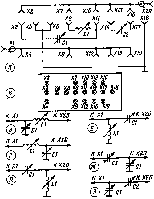
For everyday work on the air on LW bands and various experiments with receiving and transmitting antennas for Amateur radio, it is advisable to have an antenna matching device. The use of such devices allows you to create normal operation for the output stage of the transmitter (if the input impedance of the antenna is markedly different from the output impedance of the transmitter) and thereby increase the overall efficiency of the station. In addition, in some cases, the antenna matching device may provide additional suppression of harmonic components of the output signal of the transmitter, thereby reducing the risk of interference to TV.

Diagram of the antenna matching device possessing the features, shown in figure A. the Desired connection configuration matching elements L1, C1 and C2 create enabling jumpers in the contact field formed by the slots x2-X19. Possible properties of these jacks on the front panel of the device shown in figure B. the Distance between adjacent nests horizontally and vertically (with the exception of the distances between x2 and X7, X4 and X9) must be the same. This will give the opportunity to create any configuration matching elements to use only five of the same jumpers.
In addition to the P-loop (it is obtained by setting the jumper between the terminals X11-X12, X3-X5, X8-X7, X13-x14, × 17-X18) in this arrangement, it is possible to realize a further six options for the inclusion of items They are shown in figures e - W and are obtained by setting jumpers: - X3-X5, X7-X8, X11-X12; G - X3-X5, X10,-X11, X8-X9; D - X3-X4, X6-X8, X10-X11; E - X2-X3, X6-X8, X11-X12; W - X3-X5; X10-X11, X14-X15, X16-X17; Z - X3-X5, X11-X12, X14-X15, X16- × 17.
Each of these options the inclusion of elements ensures alignment with the transmitter (output impedance 50...76 Ohm ) loads with well-defined active (R) and reactive (X) components:
In - R < 50 Ω, X < 0; G - R > 50 Ω, X > 25 Ohms; D - R > 50 Ω, X < 25 Ω; E - R > 50 Ω, X > 0; W - R < 50 Ω, X > 25 Ohms; W - R < 50 Ω, X < 50 Ohms. These settings are provided if the maximum capacitance of the capacitors C1 and C2 is 200 pF, and the maximum inductance of the coil L2 is 20 mg.
Literature
Publication: www.cxem.net


