GP AT LOW FREQUENCY RANGES
Interesting design shortened GP for Amateur bands 40 and 80 meters invited David Reid (PA3HBB/G0BZF). A detailed description of the antenna and the results of the experiments conducted by the author, which led to its creation, on his "home page" <http://www.qsl.net/~pa3hbb/ll.htm>. With kind permission of the author we publish a short description of its antenna. Should keep in mind that this design RSNW has applied for a patent, so to use it without the author's consent for commercial purposes is impossible. However, this does not limit the repetition of this antenna for Amateurs our Amateur radio stations.
Originally antenna RSNW was developed as a shortened GP in the range of 40 meters. Later it became clear that it can be adapted to work on the range of 80 meters (without changing the size of the main emitter and without deterioration antenna characteristics in the range of 40 meters).
Schematically this antenna is shown in Fig. 1 (dimensions in cm). It consists of the main radiator (1), two linear loads" (2 and 3 for the ranges of 40 and 80 meters respectively) and a capacitive load (4).
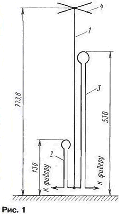
The main radiator is assembled from four segments dural tubes length 2 m each. To ensure their docking without additional elements (sleeves), used pieces of pipes of different diameters (30, 26, 22 and 18 mm, wall thickness 2 mm), which are inserted tightly into each other at a depth of 88 mm Resulting the height of the main emitter is obtained 773.6 see At the bottom it needs to be isolated from earth. As standoffs used cut plastic water pipes of suitable diameter. Reliable fixation locations connect the individual emitter elements provide a clamping collars.
The design of the capacitive load is shown in Fig. 2. It consists of four dural bands (2) a length of 100 cm, a width of 6 mm and a thickness of 1 mm. One of the ends of each bar is bent at 90* to the length of 50 mm (clamped in a vise and warming up the crease gas burner). With clamping yoke (3) their attached to the main emitter, forming a horizontal "cross". To improve mechanical stability of the "cross" design can be enhanced by installing in the center a disk with a diameter of 150 mm.
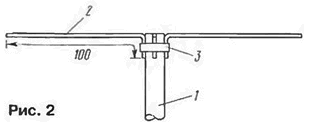
The appointment of a capacitive load is to reduce the quality factor of the emitter (i.e. to expand the bandwidth of the antenna) and raise the input impedance for the best agreeing with 50-Ohm feeder. So, a variant of the antenna without capacitive load on the range of 80 meters had a bandwidth of 180 kHz (VSWR < 2), and with this load of more than 300 kHz.
To bring the overall length of the radiator to the size, providing resonance at relevant radio bands, used in aerial so-called "linear load" (linear loading). This term indicates that to reduce the physical dimensions of the antenna instead of the focused element (coil inductance) used the change in the geometry of the emitter. When "linear load" portion of his paintings curve and forth along the main part of the radiator a short distance. It is considered that the shortening of the antenna linear load" can be increased to a value of 40% without any noticeable deterioration of its parameters. The obvious advantage of this method compared with the use of inductors - simple design and lack of appreciable ohmic losses.
The method of "linear loading" is used by some firms in the construction directional antennas, and the GAP and produces a vertical antenna with linear load".
The total length of the "line load" for GP is calculated simply: full length leaf antenna (main emitter plus linear load) must be equal a quarter wavelength for the corresponding range. When the length of the main emitter 773,6 cm length of conductors included in a "line load", in antenna would have to be 290,2 cm (range 40 meters) and 1309,7 cm (range 80 meters).
Because of the presence on the main emitter capacitive load in this design they should be somewhat smaller than these values. This shortening is not amenable to simple calculation and practice elements "line load" it is easier to pick up, taking their initially with a small margin and gradually shortening to settings the antenna at the operating frequency. To do so is easy, because transactions are made at the base of the antenna. In the author's version of a final wire length linear load" was 279 cm (minimum SWR at the frequency 7050 kHz) and 1083,2 cm (minimum SWR at a frequency of 3600 kHz).
In the manufacture of "linear loads", the author used insulated copper the wire diameter of 2.5 mm. Cut a piece of wire of the required length (with some margin - tuning), bend it into a loop, which resembles a two-wire the line closed in the upper part of the conductor in the form of an incomplete ring (see Fig. 1).
For mounting linear loads" to the main radiator (1 in Fig. 3) made of dielectric spacers (2). These spacers are fixed screw(5)directly to the main radiator. Wire (3). forming "line load", is passed into the holes in the spacers and after settings fixed with epoxy glue (4). The length of the spacers 50 mm (range 40 meters. 5 PCs.) and 120 mm (range 80 meters. 13 PCs.). Evenly distribute along the length of the loop to ensure reliable mechanical fixing. For mounting rings loop made one spacer length of 120 mm (range 40 meters) and a length of 320 mm (range 80 meters). "Linear loads" come on opposite sides of the main emitter.
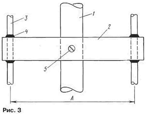
The distance between the conductors of the "line" (dimension a in Fig. 3) for the range 40 meters should be 40 mm and 80 meters -100 mm., the Diameter of the ring "linear "load range of 40 meters to 100 mm, and the range of 80 meters - 300 mm.
One end of each loop "line load" is connected to the lower end the main emitter and the remaining free ends to the feeders. Feed the antenna either separate coaxial cables or one cable that connects the high frequency relay contacts to "linear loads". Attempt to connect them at the same time to a single cable with no success. On the 40 meters band the performance of the antenna has not changed, and in the range of 80 meters it just has stopped working.
Select the dimensions of the elements of the antenna when powered through the coaxial cable with a characteristic impedance of 50 Ohms provided SWR of 1.5 within the whole range of 40 meters with a minimum SWR of 1.1 at a frequency 7050 kHz. On the range 80 meter antenna was tuned for minimum SWR of about 1.2) at a frequency of 3600 kHz. Thus in the frequency 3500 3800...kHz VSWR does not exceed 2 (at a frequency of 1.5 3500 kHz; 1,6 - frequency 3700 kHz and 2 at the frequency of 3800 kHz). These data obtained with a counterweight in the form of a grid used for poultry houses, an area of 50 sqm
A direct comparison between the shortened antenna with a full size radiator on the range 40 meters has shown (estimated correspondents of the signal level and reception stations) that they are virtually identical. In the range of 80 meters shortening antenna already exceeds 60%. so talking about a very high efficiency is not necessary. Nevertheless, it allows for DX and communication on this range.
The author has tested the antenna and four-wire counterweight length of 20 m. They were linearly loaded". to 'fit'1 in a square of size 10x10 m. While the CWS in the ranges of 40 and 80 meters has increased slightly. As one would expect, the direct comparison of two variants balances the efficiency of the antenna with wire balances was slightly worse, but all same sufficient for DX QSO on 40 and 80 meters.
LWЕ ALL-WAVE ANTENNA
Antenna, providing work stations on several Amateur the bands due to the introduction of resistors, continue to use popular among the Amateurs despite the obvious drawback - low The efficiency. The reasons for this popularity a few. First, these antennas usually have a very simple structure - the frame of a form, which includes the resistor. Secondly, because of its high bandwidth they. as a rule, do not require settings that speed up and simplify the achievement of the final result the antenna, which can be used to work on the air on several ranges.
As for the power losses in the resistor, it reaches 50%. On the one hand, loss seems to be large, but the other - ham (especially in urban conditions) may not be possible to establish more effective many-band antenna. Moreover, this order may be obvious loss even in single band antenna system. A striking example - losses in bad ground for the antenna type GP (see, for example, the article "how Much need checks and balances" in "Radio", 1999, No. 10. p. 59). To measure these losses is difficult, therefore, they just prefer not to remember.
The classic version of the broadband inclined T2FD antenna with a resistor in the frame, require to install two masts with a height of 10 m and 2 m and operating in the frequency band 7...35 MHz. repeatedly described in the literature. Interesting horizontal version of this antenna, requiring to install only one mast and running in the frequency range 10...30 MHz, it was told in the article "all-wave" ("SW magazine", 1996. No. 3, p. 19, 20). Finally, there was also vertical version this antenna.
It was proposed by L. Novates (EA2CL) in the article "Otra vez con la antena T2FD" ("URE". 1998. p. 31,32).
At a total height of about 7.5 m (see Fig. 4) this antenna provides operation in the strip 14...30 MHz, i.e. for all five high-frequency SW bands. The emitter cut the folded dipole made of two identical halves (1 and 2). They made of dural pipes with a diameter of 25 mm with a wall thickness of 1 mm. Individual sections of pipe forming the emitter, connected dural sleeves (Fig. 4 not shown). On free-standing wooden the mast (3) height of 4.5 m emitter fixed by means of cross members: two for the upper half of the radiator and two or three for the bottom.
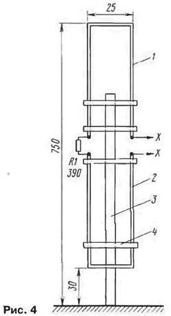
A load resistor R1 should have a power dissipation, representing approximately one third of the output power of the transmitter. Is shown in Fig. 4 the value of this resistor provides antenna impedance 300 Ohms, so supply via coaxial cable with an impedance of 75 Ohms necessary broadband balun transformer with a transformation ratio of 1:4. If you use a cable with a characteristic impedance of 50 Ohms. the coefficient the transformation should be 1:6. When using a resistor with a resistance of 500 Ohm input impedance of the antenna will be about 450 Ohms. so to power it coaxial cable with a characteristic impedance of 50 Ohms will need a balun transformer with a transformation ratio of 1:9.
Variant design of this transformer is shown in the above mentioned article about a horizontal antenna T2FD.
Balun transformer is connected to the points XX.
The only slight technical difficulty in manufacturing the antenna EA2CL is eyeliner for a power cable. To reduce the interference at his braided cable needs to be perpendicular to the blade antenna on the length of a few meters. Moreover, since, in practice, to reduce interference to zero is unrealistic, on the cable (in the the part where he is upright) it is necessary to create the inductor currents for high frequencies. The easiest solution is a small Bay formed by several the turns of the cord.
It should be noted that the antenna T2FD type work quite well in УSW the range and usually have a good SWR and at frequencies below the boundary. However, due to the small size of the radiator its efficiency in this case, of course, deteriorating. The latter, however, does not preclude the use of such antenna for short links.
Antenna with load resistor released and some firms. So the firm of Barker & Williamson produces the antenna as-1.8-30, which operates in the frequency band the 1.8 to 30 MHz and can be, in principle, installed on the roof of a house (not tower type). To install the antenna (Fig. 5) requires only one non-metallic mast (1) of 10.7 m In Amateur literature (Pat Hawker, "Technical Topics", "Radio Communication", 1996, June. p. 71, 72) is dispute about that. how to call it: whether "vertical paramba" (VHR - Vertical Half Rhombic), or "pyramid with a load" (Loaded Pyramid). This dispute can add that the antenna also reminds severely deformed T2FD. In any if it really works, and how to call it-is a secondary question.
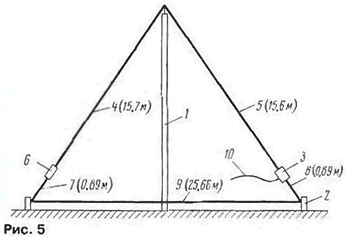
In addition to the mast (1), for the installation of the antenna need two more racks (2) height of 0.9 m. The antenna is fed through a coaxial cable (10) and a broadband balun transformer (3) with a conversion ratio of 1:9. The radiating part of the antenna - the conductors forming polirom (4 and 5).
Load resistor (6) has a resistance of 450 Ohms. Requirements for power dissipation is the same as in the T2FD antenna. Trailing frame conductors (7, 8 and 9) form a counterweight to polarama. Suspension height conductor (9) just above the surface 5 cm Should be noted that at this height suspension strut (2) can, apparently, to have a noticeably smaller height. For all conductors used copper wire with a diameter of 2 mm.
Needless to say, a load resistor and balun-matching the transformer must be protected from exposure to atmospheric moisture. It refers to the T2FD antenna, and the antenna VHR.
Using the ideas contained in the antenna VHR. it is possible, apparently, to create a very compact device on a narrow band of operating frequencies (for example. 3.5 30... MHz or 7...30 MHz) and a correspondingly smaller number of Amateur bands.


