The vertical antenna attract the Amateurs the opportunity to receive radiation at low angles to the horizon at a low altitude - the installation of the antenna and almost circular radiation pattern in the horizontal plane. In addition, such antennas, which occupies relatively little space, it is convenient if the radio cannot find a rather remote and high suspension points of the antenna.
The vertical antenna, of which the most common Ground Plane, are, as a rule, to work in the same range, especially if for matching the antenna with feeder used items configured.
Previously proposed (for example, SP3PK, UF6FB, etc.) multi-band antenna is quite difficult to manufacture and set up.
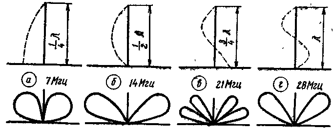
The described multi-band vertical antenna is simple in construction. In the simplest scenario it is designed to work on ranges 7,14 and 21 MHz, and with little complication and 28 MHz. The antenna height of 10 m. In Fig. 1 shows the current distribution in the antenna and the shape of the directivity in the vertical plane, depending on the ranges (i.e. the ratio of the height of the antenna and the wavelength).
From Fig. 1 shows that in the range of 7 and 21 MHz antenna is fed by a current, and at 14 and 28 MHz - voltage, so with the direct power coaxial cable on the bands 14 and 28 MHz VSWR will be unacceptably large.

Fig. 1
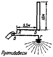
In this antenna, the task of coordination with feeder 14 and 28 MHz is solved by applying an unbalanced quarter-wave transformer (see Fig. 2).
For the matching transformer, you can use a piece of 600-Ohm line. At the same time when working on 7 and 21 MHz requires a direct connection between the cable and the antenna. It turned out that the points C and D (Fig. 2) can be combined (bending a matching cut in a circle or a triangle with smooth rounded). In this work an improved transformer. Such a combination was possible because the transformer is powered asymmetrically (with unbalanced load), and the lower wire mainly serves to create a continuous linear capacitance with respect to the upper (in the figure) wire of the transformer.

Fig. 2
If points A and B to close, the transformer will be shorted, and lived cable will be connected to the antenna socket. In this position, the antenna works on 7 and 21 MHz. A small capacitance between the wires of the transformer is connected in parallel to the antenna is supplied with a current, and has no effect on her work.
Thus there is sufficient antenna on three ranges without the use of coils or capacitors. The efficiency of the antenna is high enough, since its length is equal to or exceeds a quarter wave on all performance ranges. On 14 MHz due to the narrowing of the charts in the vertical plane of the antenna provides a gain of 1.8 dB (half power) compared to a quarter-wave vertical antenna. On 21 MHz for certain angles of radiation amplification reaches two times the power. Structurally, the antenna is an integral dural tube with a diameter of 4 cm and a length of 10 m. It is mounted on a porcelain insulator height. 12 see When working on 14 MHz at the base of the antenna develops a large RF voltage (hundreds of volts), so the insulator must have a low-loss, to ensure the minimum capacity of the base of the antenna relative to the ground.
A simple relay with two contacts, to get rid of which in this design is not yet located at the base of the antenna and is enclosed in an airtight box. Wire the transformer have a diameter of 1.6 mm, the distance between them is 12 see When you use a different wire diameter for the maintenance of the same impedance (600 Ohm), you must change the distance between the wires. Between the wires of the transformer 30 cm placed insulators made of plexiglass. Quarter-wave transformer is concave in irregular triangle with smooth curves in supported in space by means of two wooden or bamboo struts length of 1.8 to 2 m.
Band 7, 14 and 21 MHz VSWR measured by the reflectometer was Merei 1,6 (reflectometer was graduirovka for resistors with a 10% tolerance).
At a certain complication of this antenna can be turned into a four - or five-band. If you apply a quarter-wave transformer of half that length (2.6 m) the same antenna can be used and 28 MHz. Practically you can make the switch between cable and antenna impedance will be triggered by either the entire transformer, or the Board, or he zamorachivatsja completely.
For this it is enough to take one antenna relay from radio station SCR-5 and position the anchor down. When de-energized relay antenna will work on 14 MHz.
The antenna can also be configured to 3.5 MHz, by placing between the base and the ground of the extension coil with a slider that allows you to change the inductance of the coil. The cable should be connected to one of the turns of the coil (closer to the cold end). The connection point may be chosen according to the minimum SWR.
The described antenna can be classified as a Ground Plane, i.e. antennas, working with artificial ground. To do this, it must be raised to a sufficient height. If installing this antenna directly on the ground, you will need grounding, consisting of a large number of radial wires longer than a quarter wave, otherwise the efficiency of the antenna will be very low installation height of the antenna should be such that the distance between the ends of the wires - balances was less than the distance from the ends of the wires to the ground (or roof). So, for this antenna with 6 wires floor height shall be 10 m, with 8-7 m, 12-5 m, 20-3 M. Under these conditions the efficiency of the antenna will be close to maximum. The wires should have a length of 10.5 m and a diameter of 2-3 mm. Best such an antenna to be installed on the roof of galvanized iron. In this case the base can stand right on the roof. The cable jacket must be reliably soldered to the wires, soldered in turn to several sheets of iron. Worse working antenna on the roof of painted iron (due to poor contact between the sheets).
The antenna is operated at the radio station of the author within one and a half years. In the range of 7 MHz is obtained RST 599 from all continents except Oceania (589 from VK3AZZ). Established relationships with many DX.
On the bands 14 and 21 MHz RST 599 representatives from all continents obtained many times.
Author: L. Yailenko (UT5AA), Donetsk; Publication: N. Bolshakov, rf.atnn.ru


