Successful work on the bands 14. 21 and 28 MHz difficult if you have no directional rotating antenna. Very popular designs such antennas are all "squares", but, as shown, they do not possess sufficient mechanical strength.
To a considerable extent necessary mechanical and electrical requirements are met "wave channels." However, many hams are hesitant to take up the construction of mnogotirazhnoj antenna system type "wave channel" [1-4] due to the structural complexity and the large consumption of materials.


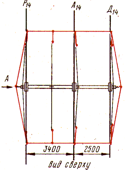
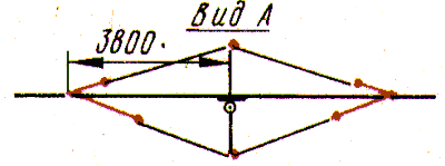
The basis of the three-element antenna is "wave channel" on the 14 MHz band, which is attached to the traverse four additional vertically mounted tube (Fig. 1). At their ends are insulating pad, through which are passed the wire antenna elements in ranges 21 and 28 MHz, which is simultaneously braces vibrators antenna on a 20-meter range. In the horizontal plane of the antenna elements in the range of 14 MHz stretched a nylon rope tied to the ends of the crosshead. To it is attached the ends of the vibrators antennas for the bands 21 and 28 MHz. Length of vibrator elements are given in table. 1. All active elements have an electrical discontinuity in the middle of the element.
Each antenna is fed via a separate coaxial cable with a characteristic impedance of 75 Ohms via a quarter-wave transformers.
Quarter-wave transformer is a line segment, the electrical length of which is 0.25 l, and the characteristic impedance is defined as the geometric mean of the wave resistance of the supply line and the resistance of the antenna, between which includes this piece. In our case we used sections of 50 Ohm coaxial cable 351 cm (range 14 MHz) 234 cm (21 MHz) and 175 cm (28 MHz).
When powered symmetric antennas on unbalanced line (coax) arise currents asymmetry flowing through the cable. This leads to the fact that the cable begins to radiate energy and, as a result, distorted and deteriorates the radiation pattern of the antenna. To combat this undesirable phenomenon using various balun device. The simplest of the bands 21 and 28 MHz can be made of quarter-wave lengths of 50 Ohm coaxial cable, is wound in the form of a single layer coil at the ends of the tube before the feed point of vibrators, and the range of 14 MHz directly on the traverse.
The described power supply system allowed us to obtain a satisfactory agreement on all ranges. Minimum SWR at resonance frequencies 14,1; of 21.15 and 28,35 MHz respectively equals 1,3; 1,5 and 1.4. Better alignment will require the use of gamma, omega - or T-initiator.
Cross member made from thin-walled steel pipe with a diameter and a length of 51 6400 mm long, the ends of which are welded, continuing, extra tube diameter 18 and a length of about 100 mm. they tied nylon stretch marks. Elements "wave channel" on the 14 MHz band is made of dural pipes with a diameter of 30 mm. They attached four U-shaped clamps with a diameter of 6 mm to a rectangular glass fibre laminate sites sizes HH mm, and those, in turn, two U-shaped clamps with a diameter of 10 mm to traverse.
Four vertical pipes with a diameter of 18 mm can be welded to traverse or attached to the orthorhombic sites with a side of 150 mm and a thickness of 4 mm two 6-mm And-shaped clamps. The platform is mounted on the traverse by means of two U-shaped clamps with a diameter of 2 mm.
Elements of antennas for the bands 21 and 28 MHz is made of copper wire with a diameter of 2 mm. They are, as already noted, passed through two holes in the insulating pads from fiberglass exchanges HH mm, which is screwed with two screws to the ends of the vertical tubes. Ropes made of nylon cable with a diameter of 7 mm.
This device is located at a height of 6.5 m from the ridge slate roof.

Of particular interest to radio Amateurs may be represented by an antenna, consisting of two three-element "wave channels" on the bands 21 and 28 MHz, where the elements of a 28-MHz antennas simultaneously serve as braces for the antenna elements in the range of 21 MHz. The geometrical dimensions of the antenna are listed in table. 2.
Literature
Author: V. Gordienko (RB5IM) Donetsk; Publication: www.cxem.net


