


")

This question is of interest to many hams. He appears, for example, if you want to connect to the antenna symmetrical two-wire 300 Ohm feeder line instead of 75 Ohm coaxial cable or, on the contrary, when replacing a 300 Ohm open line of 75 Ohm coax.
The feeder is not always possible to directly connect to the antenna, bypassing the matching device. The question of the performance of the compensated transition (or matching device) from the antenna system to the feeder line is one of the main in the design of antennas. It is aimed mainly at reducing the losses in the feeder through the provision of mode close to, the mode of the traveling wave. The main feeder line, usually the longest. Therefore, it is preferably possible to better align with the load.
Why is there a need for matching devices and what conditions need to be observed in the manufacture of complex antennas with multiple pairs of power points?
In the feeder with a given characteristic impedance of each load creates a mode that is similar to the mode traveling wave. Conversely, to obtain optimum matching of the load feeder, you will need a feeder of a particular wave resistance. It would seem that, using the graph Fig. 1, in many cases practically occurring loads, you can pick up the necessary feeder wave resistance and to ensure acceptable IPM. However, it overlooked the input (output) resistance of the equipment (TV, receiver, transmitter) to which the feeder is connected to its second end. In the case of this resistance is also fully retained the requirement for ensuring the coordination with the transmission line. Typically, the value of the input (output) resistance equipment trying to get close to the wave resistance value of the serial cables. This forces to take special measures in consultation antenna with feeder impedance which is selected with respect to the input (output) impedance of the radio.
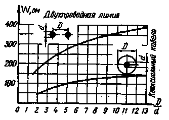
Fig.1
In the power supply system of complex antennas with multiple pairs of power points there are additional difficulties associated with the fact that the wires of each antenna element included in the lattice, it is necessary to ensure the equality of the currents in phase and amplitude.
The latter is achieved through the distribution feeders, which are connected in parallel to the Primary, for example, as shown in Fig.2,a and 2,b. Choose a distribution feeders already loaded directly on the antenna. It should be noted that the electrical length of the wave resistance of the distribution feeders, are balanced in the power circuit must be respectively equal.
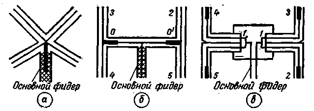
Fig.2
Parallel distribution feeders leads to the reduction of resistance and there is a need in their recovery. The more antenna elements, the more distribution feeders and tangible reduction of resistance. Powered by the scheme of Fig. 2, differs from the previous two, as in the points of connection 1-1
main feeder is restored to the value of the input impedance present at the input of each individual distribution feeder. Indeed, the distribution feeders 2, 3, 4, and 5 are enabled in pairs in parallel, and a pair of points in a 1-1 are connected to the main feeder series. When this phase of the voltage supplied to the points 1-1, are shifted relative to each other by 180°. For proper phasing of the antennas must be artificially account for this phase shift, perepolyusovka at the feed point antennas 2, 3 in relation to the antennas 4, 5. One way to address issues of harmonization is used as a distribution feeder line segments with a characteristic impedance wрасп.a feed. large, than the impedance of the main feeder wосн.feed..
For example, in the circuit of Fig. 2,and is convenient to use the line with wрасп.feed.=300 Ohms at wосн.feed.=75 Ohms as, being connected in parallel, these lines will provide mainly supply feeder to the value of IPM, which occurs in each of the distribution feeders.
To save a similar regime (Fig. 2,b) it is necessary that the segments of lines 0-3, 0-4, 0'2 and 0'-5 had wрасп.feed.=300 ohms, and line segments from points 0 and 0' to main feeder - 150 respectively Ohm when wосн.feed.=75 Ohm.
In both the first and the second cases should pick up the antenna elements to the input impedance in the frequency range provided in the distribution feeders acceptable IPM.
For matching is also used impedance transformer, in particular the series-connected line segments. Their inclusion in the power circuit shown in Fig. 2 bold lines.
Author: Candidate of technical Sciences K. P. Kharchenko; Publication: www.cxem.net