


")

All-wave, or at least working on most of the nine Amateur LW bands of the antenna is the dream of many Amateurs. Task create a multi-band antenna is substantially more complex when it comes to the directional antenna. Interesting solution it proposed in a published article. The ideas used UT1MA in this design, may be useful radioamateurs with self-developing LW antennas.
Multi-band directional antenna of the type "wave channel" for Amateur radio is very popular, they are produced dozens of companies in many countries. Such antenna mostly made using separating resonance contours - TRAP, or traps [1, 2]. Despite the obvious convenience in Amateur antenna design this technology is used very rarely that due, primarily, to the complexity of home-made and reliable the fine tuned ladder.
Recently appeared antenna design, in which the problem multi-band operation is solved in a simpler way, using the so-called multi-range load circuits (LOad Multiband or abbreviated LOM). Main element of the antenna - coil with a certain inductance, located in a certain place active or passive element. Mechanism of action LOM-load is that at a relatively high frequency coil causes a significant reflection of the current, resulting in its distribution to "docsfusion" part is close to the distribution in the normal dipole with arm length of about 0.25 λ. At low frequencies the current is distributed throughout the length of arm of the antenna and the coil works as an extension [3].
Let's compare the main parameters of the two-band dipole: the trap and with LOM-coils. The calculations were performed using the antenna of the program MMANA (TNX JE3HHT and DL2KQ for the excellent program).
In Fig.1,and shows a drawing of a dipole at ranges of 10, 20 and 40 meters. The shoulders of the dipole symmetric, which allows to simplify the figure to show only half dipole. We assume that the capacitors ladders L1C1 (the resonance frequency f1 = to 28.3 MHz) and L2C2 (f2 = 14,15 MHz) formed by the tubes inside and the outside of the coil. Note that this technologically comfortable design capacitors has a significant drawback - because of the influence of these tubes the quality factor of the coils (and the circuit in General) decreases 3…4 times and in many models does not exceed Q = 80… 100. Accordingly, at the same time increase losses in circuits and heating.
Take C1 = 25 PF, C2 = 15 pF, Q1 = 100 and Q2 = 80, and the diameter of the conductor antenna (tube) is equal to 30 mm. Plots of the dipole ab, cd, eg have a length, when which on all three bands reactive component of the input impedance close to zero.
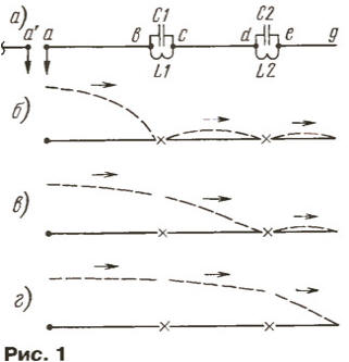
The plot changes the amount of current along the dipole on other bands is shown in Fig. 1,b (range 10 meters), Fig. 1, (20 meters) and Fig. 1,g (40 meters). The arrows on the plots show the direction of current in the respective parts of the dipole. MMANA shows that the parts of a dipole located at the ladders, also have a small current, which appears as a result of interference from the work area the antennas.
At a range of 10 meters this current significantly, by about 0.4 dB, increases the antenna gain by narrowing the directivity (NAM) and also increases the input impedance of the antenna.
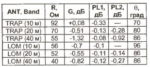
The results of the calculation are summarized in the table. It R is the input resistance the antenna at resonance. The gain G is given relative to a half-wave the dipole without traps.
Separate total heat losses in the two coils PL1 and two PL2, because of these losses affect the reliability of the antenna. G is the width the main lobe -3 dB or 0,707 from the maximum. In the evaluation of thermal losses can assume that 0.1 dB corresponds to approximately 2.4% of full power. Full length dipole - 2x6,7 M.
In Fig. 2,and depicts the dipole at ranges of 10, 20 and 40 meters, but, in unlike the first, it used the ladders, and LOM-coil. The values L1 and L2, the lengths of segments ab, cd, eg and capacitive loads IN and IN selected, so on all three bands reactive component of the input impedance was close to zero. In particular, the length of the initial segment ab will be about a 0.25 wavelength range of 10 meters. Due to the presence of L1 in this range the shape of the current curve on the ab phase is almost the same as a half-wave dipole.
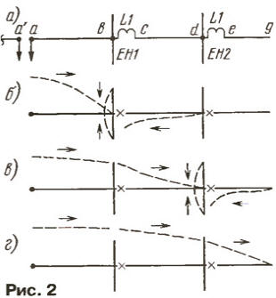
The current for the coil on a plot of cd several times smaller than first a plot. This is important because here the current has reversed direction and is leads to the extension of the NAM and, consequently, a decrease in the gain of the dipole. To to minimize this undesirable effect, introduced by the capacitive load IN, which "takes over" and excludes from the radiation part of the counter current. Value current plot cd also depends on the inductance of the coil L1 and will be the least, the larger it is. On the other hand, the increase of the inductance of the coil leads to the reduction of bandwidth in the second range (20 meters), so the choice the inductance of this coil is an inevitable compromise. In the range of 20 meters similarly, the elements L2 and IN, and coil L1 works as lengthening. In the range of 40 meters both coils - lengthening. Distributions of currents along the conductor of this variant of the dipole are given in Fig. 2,6 (10 meters), Fig. 2, (20 meters) and Fig. 2,g (40 meters).
The calculation showed that the optimal values are L1 = 3,5 mH and L2 = 18 mH. The total length of the dipole 2x5,8 m in diameter of the tubes 20 mm in the last parcel and 30 mm on the others. Length EN - 0.8 m and EN - 0.6 m tube diameter of 16 mm. Design parameters are also given in the table, which is convenient for comparison. When the calculation of the quality factor of the coils L1 and L2 250 accepted that it was realistic.
Comparison of heat losses in the TRAP and LOM-dipoles shows that second loss in 2…3 times less. At identical other design conditions LOM-antenna able to withstand more power. However, if the traps, you can use external capacitors, both types of antennas according to this index approximately equal.
A useful property LOM antenna is impaired to the value of the inductance of the coils. When the deviation from the estimated value by 10 % resonance tuning is easily restored by adjusting the length of the elements YONG. The antenna parameters change slightly. Also obvious advantage - no need to apply high-voltage capacitors, designed for large reactive power.
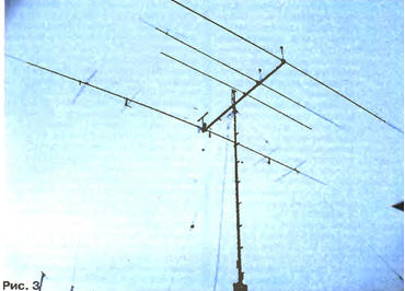
After successfully using LOM technology in multi-band vertical the antenna [3, 4] the author has attempted to apply this technology in the active vibrator (AB) a simple directional antenna for seven LW ranges from 10 to 40 meters. AB designed for use with one 50 Ohm feeder without any switching. Besides AVI, the structure of the antenna is composed of five reflectors bands 10, 12, 15, 17, 20 meters, and at ranges of 30 and 40 meters in antenna works only active vibrator. The appearance of the experimental antenna, received the author's name BMA-7 (Beam Multiband Antenna with 7 bands), is shown in Fig. 3.
A schematic electrical diagram of the active vibrator shown in Fig. 4. Each arm of the AB (conventionally shown only one of the two) consists of four conductors, the beginning of which converge at the point of supply.
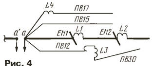
Structural basis of the antenna is the Central vibrator, consisting of three segments duralumin tubes, which are located between the coils L1 and L2. This the vibrator operates at ranges of 10, 20 and 40 meters. The bands 15 and 17 meters. provide wire vibrators PV and PW. Coil L4 with a small inductance can reduce the length of the vibrator PV need to constructive considerations sizes. In the range of 12 meters works a vibrator PV, and together with the coil L3 and the additional conductor on the obtained PVT the emitter of 30 meters. Naturally, between the constituent parts AB there is a mutual influence, but nevertheless, on the whole is clear seven resonance and SWR at medium frequencies of all bands in the range of 1.1 to 1.4… (only AV - without reflectors).
A more detailed drawing of AB with the main dimensions in two projections schematically is shown in Fig. 5.
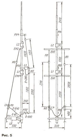
Wire vibrators PV is made of stranded wires in vinyl insulation brand pvz section 2.5 sq mm For wire support vibrators used small Marinova insulators IO and plastic antenna insulators PI firm Antinopolis" (Zaporozhye). These insulators have a size 17x17x115 mm and four holes - two on the sides and two in the middle. Coil L4 has 7 turns and are wound directly on the middle part of the insulator of the wire emitter PV. Wire emitter PV fixed at some distance from the Central vibrator dielectric spacers RP. Far from center antenna) the ends of the emitters PV and PV recorded using polypropylene stretch marks on the PP tube IN.
Reflector range of 10 meters made of pipes with a diameter of 20 mm and has a length 5.3 m, range 15 meters of tubes with diameters of 30, 20, 16 and 10 mm (total length is at 7,235 m), range 20 meters from tubes with diameters of 30 and 20 mm (total length is 10.51 m). The distance from AB to reflectors ranges of 10, 15 and 20 meters amount of 2.05, 2.6, and 3.7 m, respectively. Reflectors bands 12 and 17 meters made of stranded wire with vinyl insulation brand THP - 2.5 and are arranged respectively above the reflectors 15 and 20 meters (see Fig. 3) such a way that the middle part of the wire reflector pipe above 0.5 m, and the ends of 0.2 m. the total length of the reflector range of 12 m to 5.5 m , range 17 m - 7,75 m Capacitive load - out of the tube diameter 16 mm, length EN - 1.3 m and AN - 1.6 m. These coils : L1 - frame with a diameter of 33 mm, wire MGTF section 1 sq mm, number of turns - 9, the winding dense, waterproofing tape NOVA ROLL; L2 - frame with a diameter of 32 mm, MGTF 0, 75 sq mm, number of turns - 24; L3 - frame with a diameter of 40 mm, MGTF of 0.75 sq mm, 18 turns.
The antenna is experimentally simulated on the first layout, and then had a real sample. Active vibrator configured by using the bridge SWR meter: ranges 10 and 20 meters by changing the length of capacitive loads, and the range 40 meters by changing the length of the terminal segment. Other bands set the selection of the lengths of wire vibrators. The length of the wire reflectors for the presence of vinyl insulation on the wire and the proximity of the tube reflectors it was difficult to calculate, they are configured by using the gear on the frequency, different from the average frequency of a given range of 3 % down. Full length active vibrator - 2x6,35 m.
After receiving a computer program MMANA calculation of active vibrator (the ranges of 10, 20 and 40 metres) showed how it is possible to obtain the same parameters when the reduction of the lengths of the YONG and the total length of the active vibrator (see above the settlement data).
The power cable is aligned with AV with just one additional item - the capacitor 56 pF/2,5 kVA, connected in parallel to the input of the antenna. The balancing is done using a protective inductor L5 15 turns the coaxial feeder cable RG-58, wound on an annular territoiy the magnetic core with a diameter of 65 mm from the material IN. The throttle and matching the capacitor is placed in a protective casing and mounted on a steel spacer in WP1 the centre AB, support elements PV and PW. It should not be forgotten (if the modeling of the antenna, in particular) that the segments of the wires going to the transformer (length about 10 cm each) are in electrical length AV.
The Central part of AB (to the coils L2) is made of a tube with a diameter of 30 mm, and end segments of tubes with a diameter of 20, 18 and 10 mm, inserted in one another.
The antenna is supplied with a cable RK50-7 length of 30 meters.
After a slight correction of the lengths of the elements AB obtained the following values: CWS - at medium frequencies ranging 1,1 1,4…; operating frequency range for VSWR ≤ 2 is in the range of 10 meters 1 MHz, band 12, 15 and 17 meters - 0.5 MHz, the range of 20 meters to 0.32 MHz, on 30 meters - 0,09 MHz and in the range of 40 meters - 0,18 MHz. The measurements were carried out by the device WH7 firms DRAKE.
Check antenna "on the air" showed that the ratio of forward/backward medium slopes in the range of 20 meters is in the range 12…15 dB, upper ranges - 15…18 dB. On 40 meter range when compared with the antenna Inv. V it turned out that in the direction of maximum radiation of the antenna BMA-7 not inferior to the full-size Inv. V, but in a lateral direction surpassed 1 2… points. The calculated values of the gain ranges 10…20 MHz make 4…4,5 dBd.
Is it possible improvement of the parameters of this antenna by adding of Directors? It it is quite difficult for the following reasons. First, the Directors of the lower ranges significantly degrade the top options. To eliminate this phenomenon have to enter drains, LOM-ka-carcasses or take other special measures. Secondly, you will have difficulty applying standard methods of agreement when one the feeder due to the variation of input resistance at different ranges.
Perhaps it is described in the form of the antenna may be of interest to the "average" of shortwave. Parameters antenna BMA-7 close to automatic process the antenna length 6…8 meters, but it has the elements on the ranges of 30 and 40 meters.
It may also be noted that among the Western Amateurs is popular simple antenna C4 firm FORCE-12 with the length of the boom 3.6 m, with two elements in the ranges of 10, 15, 20 meters and 40 meters band when two feeders (the price is about 700 USD).
In conclusion, we can say that, as shown by this work, LOM-technology successfully applied in multi-band antennas, competing on an equal footing with TRAP technology.
The author is grateful to Boris Kataeva (UR1MQ) for their invaluable help in the editing process and settings antenna BMA-7.
Literature
Author: E. Gutkin (UT1MA), Lugansk, Ukraine