


")

The radiation resistance of such quarter-wave antenna is equal 28-32 ohms (depending on the outer diameter of the metal tubes, of which it is built). Therefore, the connection of the antenna with a 50 - or 75-Ohm coaxial cable will lead to the appearance of a standing wave and to the loss of energy. For matching vertical pin cable is required to use additional elements - inductors, capacitors or sections of cable with certain parameters.
Below is described a simplified method of calculating the antenna "Ground plane" with a horizontal counterweight and a matching cut cable. Antenna constructed according to this calculation, work well for one Amateur band (for example, 14 MHz) and, however, quite satisfactory and emit at two adjacent bands (21 and 7 MHz).
The calculation will result in a numerical example for the 14 MHz band. Pin connection with a supply cable and a matching cut cable and denote their sizes are shown in Fig. 1.
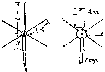
Fig.1
For the calculation you need to know the diameter metal tubes or wires, of which will be performed with the probe antenna and the rays of the counterweight. Assume that we are going to use for the manufacture of the antenna tube with an outside diameter of 30 mm,
and the counterweight will be made from a wire with a diameter of 2 mm. determine the coefficient M, which characterizes the ratio of the length remote from the ground a half-wave dipole to the diameter of the antenna. Apply the formula:
M=150000/(f(MHz)D(mm))
Here f is the average frequency,
D is the diameter of the tubes. When f=14.2 MHz and D=30 mm, we obtain:
M=150000/(14,2*30)=352
The coefficient M is defined, using the graph (Fig. 2), the radiation resistance of a quarter-wave antenna Rизл (resonant frequency): Rизл=30.8 Ohm.
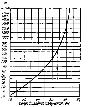
Fig.2
Now we should calculate the true radiation resistance Ry shortened antenna, which we will build; it is due to the influence of the earth and of the counterweight is different from Rизл and is equal to:
Ry=Rизл-Z/4Rизл
Here Z is the wave impedance of the coaxial cable, from which the feeder. In our example, we take it equal to 75 ohms. Then:
Ry=30,8-75/4*30,8=30,2 Ohms.
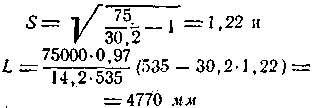
To calculate the length of the vertical pin L need on schedule Fig. 3 to define two auxiliary factor: the COP describes the change in resistance of the antenna when changing its length, and KZ, considering the influence of the counterweight and the earth's surface. Received: Kc=535, KZ=0,97.
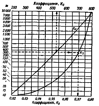
Fig.3
The schedule for the determination of the coefficient K can be used only when changing the length of the antenna is not more than 10%. If the antenna is longer than the resonance, the impedance is inductive, if shorter - capacitive.
The length of pins (mm) is determined by the formula:
We;
To determine the length of the rays counterweight Lnp made of wire with a diameter of 2 mm, the calculated M:
M=150000/14,2*2=5280 and on schedule Fig. 3 find Ky=0,978. Then
A shortened antenna has, in addition, also the reactance of the capacitive nature. To compensate parallel to the antenna attached shorted on the cut end of the cable; the length thereof is selected such that its reactance is inductive had the nature of the required size. Determined by this inductive reactance:
Xc=Z/S=75/1,22=61,5 Ohms
Using a slide rule or a table of tangents, find the angle a, the tangent of which is numerically equal to the ratio of the values obtained Xc to the characteristic impedance Zc of the cable from which the matching segment. When Zc=75 ohms:
Xc/Z=61,5/75=0.82 and a=39,4°
The length of the shorted segment is equal to:
Lc=(833ab)/f, mm
In this formula, b is a coefficient characterizing the velocity of propagation of energy through the cable. For common cables with continuous filling (RK-1, RK-3) b=0,67.
Therefore,
Lc=(833*38,4*0,67)/114,2=154,9 mm
As described above, the calculation takes into account that the rays of the counterweight are arranged horizontally; however, when the inclined position (at an angle of 30-40° to the ground) the error term is negligible.
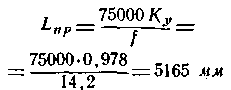
The standing wave ratio (SWR) in the feeder can be measured by collecting simple pointer SWR bridge type, the diagram of which is shown in Fig. 4. Here the resistance R1, R2, R3, and radiation resistance of the antenna form a bridge. In one of its diagonals is served by the high frequency energy from the transmitter (Per connector). In the second diagonal of the diode D1 included type DE.
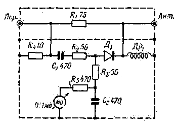
Fig.4
The resistance R4 serves to reduce the output resistance of the power source (transmitter). Throttle (DR1) closes the circuit of the permanent components of the rectified current, it is necessary in the case that the antenna circuit has no galvanic conductivity.
When bridge balance the meter pointer is not rejected. Misalignment of the antenna and the cable causes the appearance of standing will, it is noted that the deflection of the needle. The measured VSWR is as follows:
1. Set up the transmitter with the antenna at full power output.
2. Reduce the power to zero, locking, for example, one of the lamps prior cascades negative offset, and disconnect the antenna.
3. Connect the cut cable transmitter input connector and TRANS. on the index of the CWS.
4. Gradually, very gradually, so as not to burn the resistance R4, increase the capacity of the energy supplied to the pointer of the CWS, up until the meter pointer will deflect to the end.
5. To check the balance of the bridge is temporarily attached to the Ant in connector 75 Ohm; the needle of the milliammeter should be at zero.
6. Turning to the Ant in connector. coaxial cable feeding the antenna, say on the scale of the current and determine the VSWR curve depicted in Fig. 5.
Fig.5
If the feeder of the antenna does not introduce significant losses, for example he made of cable RK-1 or RK-3 and has a length of no more than 15-20 m SWR 2 and even the 2.5 is perfectly valid. Total losses (sum of losses in the feeder and losses due to mismatch) in this case will not exceed 0.5 dB. This decrease in power at the receiving station at the hearing will not be marked. A noticeable drop in the volume of intake (1-2 points) can be observed only when the CWS 5-8.
In that case, if built antenna SWR is overloaded or its size is chosen larger or smaller than it should be, it is necessary, using a pointer CWS, adjust the antenna empirically. The antenna is more than you need, the length may be electrically short the capacitor, in series with the vertical part (Fig. 6,a). Too short antenna can be electrically lengthened by adding thereto the inductance (Fig. 6,b). In this case, the configuration of the antenna lead alternately, selecting the position of both tweaks on the coil. Here a part of the coil tweaks between 1 and 2 is used for lengthening the vertical part of the antenna, and the lower part (2-3) replaces matching shorted cable section (Fig. 1).
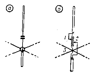
Fig.6
In conclusion, we note that the antenna of the type described accumulate charges of static electricity, especially when approaching storm. Therefore, it is recommended to use the antenna with a shorted cable segments (Fig. 1) or shunt cable inductance (Fig. 6 b), and securely grounded cable sheath.
Author: Y. Prozorovsky (UA3AW); Publication: N. Bolshakov, rf.atnn.ru