Emil Taro proposed construction and tested several types of antennas based on a rectangular wire frame with an aspect ratio of 1:3. The advantage of such a framework antennas in the small height of the suspension, provided that the short side is vertical. For example, a frame for the 40-meter band (Fig.42) it is enough to lift to a height of about 10 meters, so that its lower side was 5 metres from the ground.
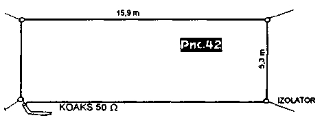
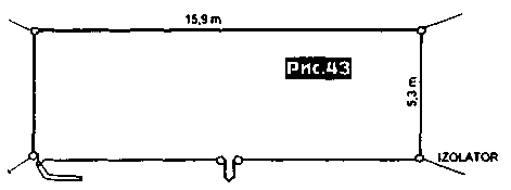
Powered frame 50 Ohm coaxial cable. To adjust the frame until the SWR is 1:1 in a predetermined part of its range it is useful to include in the gap of the bottom side of the frame a short-circuited loop (Fig.43).
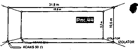
It is possible to make a dual band antenna, for example for 80 and 40 meters, placing inside the frame 80 m antenna on 40 m (Fig.44).
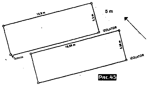
For those wishing to get a more efficient antenna, you can offer to complement the active frame, for example a reflector (similar design for 40 m band shown in Fig.45) or to add one or more of the framework of Directors.
Was built 4-element antenna with an aspect ratio of 1:3 to 40 meters and it has also been tested in comparison with a 3 element full size Yagi placed at a height of 45 meters. Both antennas were fixed direction on the United States. Out of 100 ties with American hams 90 gave preference to the strength of the framework from the antenna and 100 correspondents were better heard on a "framework" than the Yagi. Thus the range of 40 meters in the direction the U.S. is "opened" by 30...45 minutes early and "closed" at the same time later when using a 4-element loop antenna. In Fig.46 shows a diagram of a dual band (40 and 80 meters) double loop antenna.
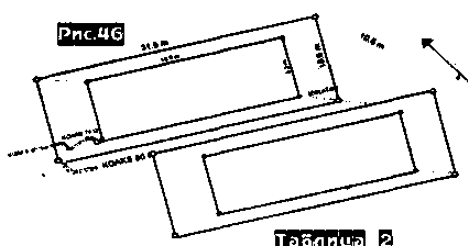
Since the distance between the selected optimal for 80 meters and is equal to 10.6 m, 40 meters is a lot, and had to take additional measures to harmonize active vmci 40-meter band with 50-Ohm cable by incorporating between the feed points of the frame and the 50-Ohm feeder quarter-wave cut 75-Ohm-tion of the cable (its physical length taking into account the velocity factor is equal to 7 meters). In table.1 are given the measurements of two-element antennas for five bands.
Table 1
Range, MHz
Active frame
Reflector
The distance between frames, m
Short side, m
The longest side, m
Short side, m
The longest side, m
3,5
10,60
31,80
11,13
33,39
10,20
7
5,30
15,90
5,56
16,68
5,00
14
2,67
8,01
2,80
8,40
2,50
21
1,78
5,34
1,87
5,61
1,70
28
1,33
3,99
1,39
4,17
1,27
Author: Emil Taro, T99W; Publication: N. Bolshakov, rf.atnn.ru


