


")

Special attention is also drawn to a thorough welds all elements of the antenna. Since aluminum is difficultly solderable - it is rarely used in loop antennas. Often used copper tube diameter of 12 to 50 mm.
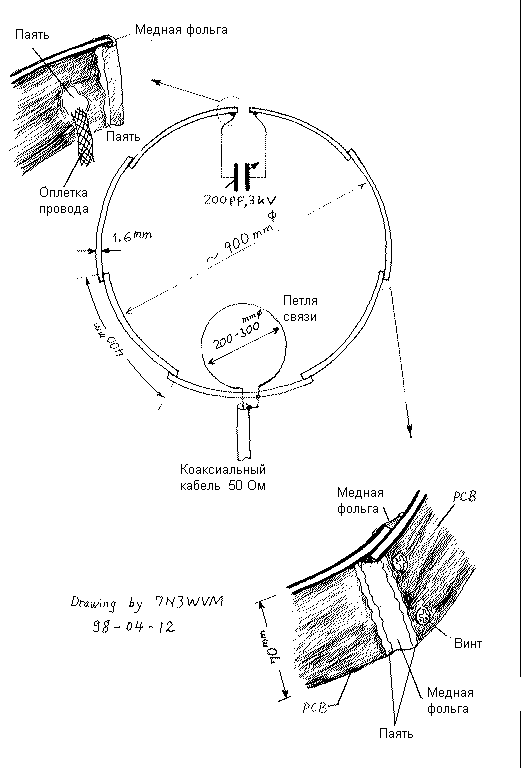
Despite all this, I made a magnetic loop antenna of strips of foil fiberglass. They are pretty light, well soldered and is much cheaper than copper pipe. The foil on the glass fiber is pretty thin, so You might think that it has a higher resistance compared to copper tube. However, we must remember the "surface effect", which appears at high frequencies. Thus, a thin foil is not as good in comparison with a thick copper tube. The thickness of the conductor does not matter at high frequencies. For example, for copper, if the signal frequency of 10 MHz, the depth of the existence of "surface effect" only 21 microns, and with increasing frequency, it decreases inversely to the square root of the frequency. Here the main area and therefore a large surface of the foil may be even more effective than the copper pipe!
The thickness of the copper foil fiberglass about 50 microns. If for a frequency of 10 MHz is enough 21 microns, the antenna is made of such material will work well at higher frequencies.
For the manufacture of antennas are used strips doctoronline foiled fiberglass length of 40 cm and a width of 7 cm Only need seven bands. The total length of tape will be about 270 cm, and the diameter of the resulting loop will be about 90 see the joining strip is visible from the figure. Each band overlaps with a connecting strip 2 see All joints tightly pulled together by two screws. Both sides of the strips of fiberglass are connected by a copper foil, and soldered on both sides of the plate. This increases the effective area of the antenna. Findings to a variable capacitor made of copper braid cable and carefully soldered to the plates. Simple screw connection is not allowed here because of low efficiency.
The rest of the design is slightly different from the conventional loop antenna and clear from the figure.
The results of the experiments. Made the loop was installed horizontally on the outside of the window of my apartment (1st floor of a five storey building). From the earth to the loop was 3 meters, and from the walls of the house - 1.3 m. the SWR was 1.5 and for ranges less than 10 MHz and 14 MHz. within a few months after the manufacture of the antenna, I worked with stations throughout Japan, Okinawa and one station from Korea in the range of 10 MHz CW transmitter with a power of 3 watts. On the 14 MHz band spent a connection with the far Eastern stations, such as Korea, China, the Asian part of Russia, Taiwan and Hong Kong when the same transmitter power of 3 watts. I live in Chiba - East of Tokyo 30 km.
Literature:
1. Transmitting Short Loop Antennas for the HF Bands, I1ARZ Roberto Craighero, Communications Quarterly 1993 Summer/Autumn.
2. Small High Efficiency Loop Antennas for Transmitting, The ARRL ANTENNA BOOK, 17th EDITION, pp.(5-11)-(5-16).
Translation Nikolay Bolshakov (RA3TOX); Publication: N. Bolshakov, rf.atnn.ru