Of course, not everyone is able to manufacture or purchase the rotator, mast or farm, a large number of constructive materials. In addition, quite often the "antenna farm" radiolubitelskie station is limited to a few square meters of the roof. Not accidentally, many radiosports, especially beginners, timidly connects to participate in the competition, explaining that, usually, the lack of complex antennas.
In connection with the above, the author of these lines would like to inform the readers about the results of years of the experiments conducted by the team UZ3QBM with the simplest types of antennas and their use in sports and casual DX work.
We fully agree with the master of sports V. Uzun (UB5MCI), in his article "How to become a champion" (Radio, 1979, # 3 and # 4) wrote: "...the Lack of radio multi-element rotating antennas should not be cause for refusal to participate in the competition".
Indeed, having even a simple, but quality made and well tuned antenna, clearly presenting their properties, objectively assessing the capabilities of the equipment and properly selecting tactics for upcoming competitions, of course, you can achieve good results. They will undoubtedly grow with the accumulation of experience and improvement of the whole complex of sports equipment.
Suppose, however, that your experience and technical capacity is limited. Well, then the solution can serve as the construction of a vertical whip antennas. Their design when the length of the radiator is equal to a quarter wave length is described in detail in the literature. With the increasing size of more than half of the wavelength in the radiation pattern in the vertical plane petals appear aimed at very small angles to the surface of the Earth. When pin length 5l/8 radiation at small angles reaches a maximum. This property was agreed to be used in the artificial antennas for high frequency Amateur LW bands.
The system is as follows. The emitter length 5l/8 electrically lengthened series inductance up to 3l/4, and the radial conductors (balances) have a length of l/4. Thus, from the emitter inductance and balances was as if it were a wave dipole. The change in the resonant frequency and coordination with line power is achieved primarily by the inductance, which is a critical element of the whole system.
The table shows the size of such antennas on the bands 14, 21 and 28 MHz.
Table 1
Range, MHz
The length of the pin, m
The average diameter, mm
Length balances, m
The inductor
Diameter, mm
The length of the winding, mm
The number of turns
The wire diameter, mm
14
13,2
32
5X5,3
35
80
11
4
21
8,7
28
5X3,5
25
50
10
2,5
28
6,6
22
5X2, 62
25
50
6
2,2
All warchanter emitter is mounted on the insulator and formed with reduced diameter at the top. For the 10-meter band it is composed of two parts, and for 15 - and 20-metre respectively three and four dural tubes secured the necessary number of marks. Protivogazy made from antenna cord and connected between sobti at a point between the pin and the basis of his (long pipe), isolated from them. At an angle in the range of 95...105° to the emitter balances down to the roof. The antenna is fed by a coaxial cable with a characteristic impedance of 75 Ohms arbitrary length.
Several technological advice on making inductors. Since the coils are in current antinodes, they must be done in such a way that they retain their geometry when changing the signal. The antennas for the bands 21 and 28 MHz coil performed on the frames of insulating material on which there is a groove with a specified step. Antenna for 14 MHz coil frameless. She wound copper tube with a 4 mm diameter mandrel with a diameter of 35 mm. After removal of the mandrel on the coils of the coil screw three plates of organic glass dimensions 5X12X100 mm drilled in them with the necessary step holes with a diameter of 4.2 mm., These kind of "ribs" at an angle of 120° to each other.
Antenna configuration was limited to determining the resonant frequency and, if required, its correction by changing the inductance of the coil. When this operation is achieved minimum SWR at the selected frequency.
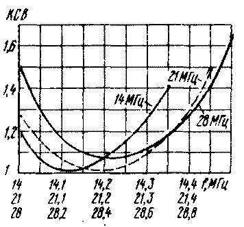
Well tuned antennas have a wide bandwidth, resilient to climate change and the underlying surface characteristics. Measurements have shown that the CWS on the 14 MHz band does not exceed 1,4, on 21 MHz - 1.5, 28 MHz - 1.8 (Fig. 1). The minimum value at the resonance frequencies respectively equal to 1, and 1.02 and 1.08 zone.

Fig.1
The quality of whip antennas were estimated using statistics in comparison with various antennas for the respective ranges. It was conducted more than a thousand of valuation comparisons in relationships with correspondents, arranged from several hundred to several thousand kilometers.
The most interesting are the data with regards to a quarter-wave pin. At a distance of 2000 km antenna made "lost" him on the scale S to 1.5 points. This is due to the fact that although in their radiation patterns in the vertical plane are the petals at an angle of about 30", but the radiation intensity in that direction less than that of the traditional CP. With increasing distance to the recipient begins to show the advantage of radiation at small angles to the horizontal and at a distance of 4000...5000 km pin length 5l/8 "wins" on average 1 point. On extended lines,...2000 to 10000 km, the signal level on both the reception and the transmission increases by 1.5 to 2 points. The most noticeable advantage created by the antenna with the links on the so-called "long way" and on routes passing through the polar cap.
Thus, despite the simplicity of the designs and small material costs, such systems show good results in Amateur practice. It is pointless to dispute the advantages of multi-element antennas, however, the years of operation of whip antennas, indicate that they allow a student to engage in sports and DX-work in the air.
The outward simplicity of these designs occupy a certain space, which is very often limited.
It is quite natural desire to increase the efficiency of their operation. However, finding any compromise solutions can negate all the positive properties.
There is no doubt that any of the above odnodiapozonnaya antennas can be coordinated on all Amateur bands, but this problem was not set, as all bands do not get an optimal result. Why were tested dvuhterabaytnye options, the idea of which was to link a quarter-wave GP for more low frequency band and pin length 5l/8 for high frequency. So the emitter length 5l/8 to 28 MHz was used as an elongated pin quarter-wave on 14 MHz, for which the total number of balances doubled, half of them has length 2,62 m, and the remaining 5.3 metres At the base appeared the switching element is a relay that on the 20-meter band connects the Central conductor of the feeder to the variable capacitor (100 pF), and the 10-meter into the inductor. Structurally, the condenser is a piece of coaxial cable. Relay RMP whose contacts are protected from moisture.
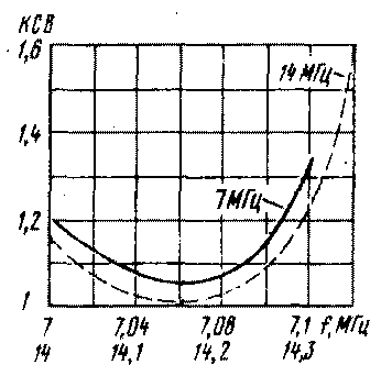
The same pattern is made antenna on bands 7 and 14 MHz. However, it had little to reduce the length of the vertical part to 12.55 m so that emkosti of kondensator included on the 40-meter range, not too low, as in the case of the emitter length of 13.2 m. In the final version, it was equal to 180 pF. The total number of balances - eight - four length 5.3 m are uniformly located on a circle, four length of 10.8 m stretched to fit the shape of the building. The rest of the design features of both dvuhtsepochnyj antennas are the same as in the above-described embodiments.
The appearance pereklyuchayusch elements special difficulties should not cause. For patania relay cable and extra wire. Fundamentally it is possible to supply power and Central vein, "unleashing" high-frequency and constant components.. In Fig. 2 shows the dependence of VSWR with frequency.

Fig.2
All antennas, which were discussed in the article, for several years operated and collective radio station and the radio station of the author. They repeatedly said hams. The antenna was enough tech, showed the stability of its parameters.
Author: G. Bolotov (UA3QA) Voronezh; Publication: N. Bolshakov, rf.atnn.ru


